
Voice input apparatus

a voice input and microphone technology, applied in the direction of loudspeakers, mouthpiece/microphone attachments, microphone structural associations, etc., can solve the problems of unintentional recognition of voice output from speakers as control commands, voice control mode activation, sound output from speakers interfering with voice recognition, etc., to prevent noise and prevent sound from being transmitted

Active Publication Date: 2022-10-11
LG ELECTRONICS INC
View PDF4 Cites 0 Cited by
  • Summary
  • Abstract
  • Description
  • Claims
  • Application Information

AI Technical Summary

Benefits of technology

The patent describes a voice input apparatus that prevents noise from interrupting what a user is saying and prevents the sound from a speaker from being recognized as a control command. This is achieved by creating a pathway for the voice to pass through and being sealed to prevent noise from entering. The apparatus also includes a sealer that blocks the transmission of sound from the speaker room to the microphone, preventing unintended control commands. Overall, the apparatus inhibits interruptions and ensures accurate voice input.

Problems solved by technology

However, in the voice input apparatus, in some cases, the sound outputted from the speaker is unintentionally recognized as a control command.
However, if the sound outputted through the speaker is similar to the specific command, there is a problem that the voice control mode is activated.
In addition, when the output of the speaker and the input through the microphone need to proceed simultaneously—e.g., when it is necessary to recognize the voice through the microphone while music is being played through the speaker—there is a problem that the sound outputted from the speaker interferes with voice recognition.

Method used


Image

  • Voice input apparatus
  • Voice input apparatus
  • Voice input apparatus

Examples


Embodiment Construction

[0039]Hereinafter, preferred embodiments of the present disclosure will be described with reference to the accompanying drawings. In describing the present embodiment, the same designations and the same reference numerals are used for the same components, and further description thereof will be omitted.

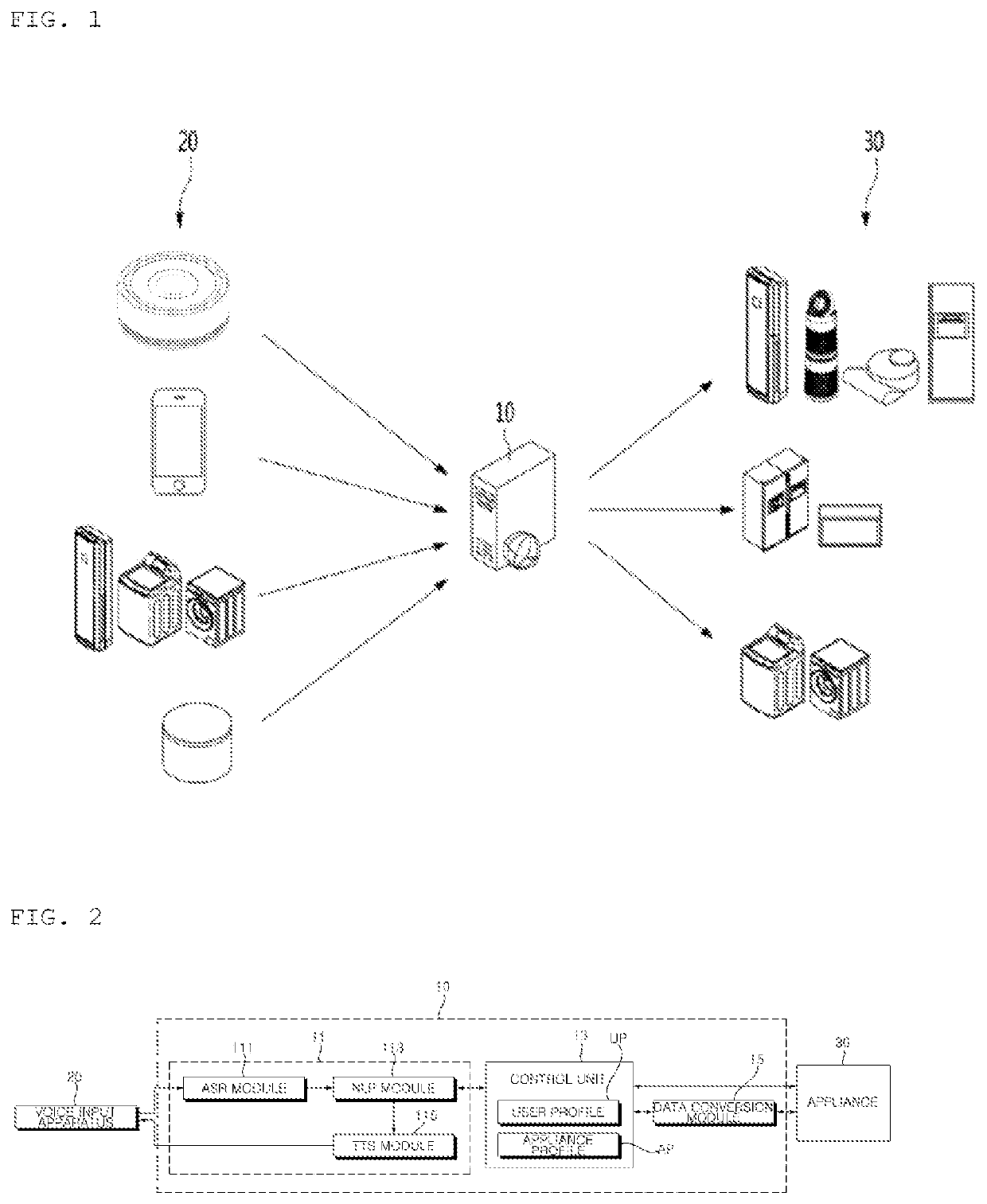
[0040]FIG. 1 is a conceptual diagram of an appliance control system according to an embodiment of the present disclosure. Referring to FIG. 1, the appliance control system may include an appliance control apparatus 10, at least one voice input apparatus 20, and at least one appliance 30. The appliance 30 is not limited to a home appliance used at home, and may be an office appliance used in a work space.

[0041]The appliance control apparatus 10 may receive various types of control commands from the voice input apparatus 20, and transmit a control signal based on the received control command to the appliance 30.

[0042]The appliance 30 may include a communication module for communication ...


PUM


Abstract

A voice input apparatus of the present disclosure includes: a panel in which a voice input hole is formed; a circuit board which is disposed below the panel and has a voice passing hole formed in a position corresponding to the voice input hole; a first sealer having a cylindrical shape which is disposed between the panel and the circuit board, an upper end of which is in contact with a bottom surface of the panel while surrounding the voice input hole, and a lower end of which is in contact with an upper surface of the circuit board while surrounding the voice passing hole; a microphone which is disposed below the circuit board and has a sound receiving hole provided in a position corresponding to the sound passing hole; and a second sealer in which an accommodation space having an opening in an upper surface thereof is formed, and the microphone is disposed in the accommodation space, and which is in contact with a bottom surface of the circuit board in a state where the upper surface surrounds the voice passing hole.

Description

CROSS-REFERENCE TO RELATED APPLICATIONS[0001]This application is the National Stage filing under 35 U.S.C. 371 of International Application No. PCT / KR2019 / 008649, filed on Jul. 12, 2019, the contents of which is incorporated by reference herein in its entirety.TECHNICAL FIELD[0002]The present disclosure relates to a voice input apparatus that receives a voice for controlling an appliance.BACKGROUND ART[0003]There are various appliances, such as TV, air conditioner, audio, cleaner, washing machine, air purifier, clothing manager, refrigerator, oven, dishwasher, water purifier, and dryer, in the home. The appliances are controlled by a wireless communication-based remote control apparatus. In general, a single control apparatus controls a single appliance, but there is an integrated control apparatus that manages and controls several appliances together.[0004]With the development of voice recognition technology, recently, a control apparatus for recognizing a user's voice command and ...

Claims


Application Information

Patent Timeline
Patent Type & Authority Patents(United States)
IPC IPC(8): H04R1/34H04R1/02H04R1/04H04R1/08H04R1/28H04R3/00H04R7/12
CPCH04R1/345H04R1/025H04R1/04H04R1/08H04R1/288H04R3/00H04R7/12H04R2201/028H04R1/2803H04R7/02H04R1/021
Inventor YOON, YOUNGSIK
Owner LG ELECTRONICS INC
Learn More