
Static gasket with wire compression limiter

a technology of compression limiter and gasket, which is applied in the direction of engine sealing, metal-working apparatus, sealing arrangement, etc., can solve the problems of fatigue cracks forming in the area of compression bead, reducing the life and performance of the engine, and reducing the service life of the engine, so as to achieve a stronger, reliable seal, and increase the combustion pressure

Inactive Publication Date: 2013-08-29
FEDERAL MOGUL MOTORPARTS LLC
View PDF4 Cites 0 Cited by
  • Summary
  • Abstract
  • Description
  • Claims
  • Application Information

AI Technical Summary

Benefits of technology

The present invention provides a flexible gasket with a compression limiters that can create a strong and reliable seal between parts, allowing for increased combustion pressures and higher combustion efficiencies. The gasket also has a variable topography to provide different sealing pressures in different areas to optimize performance. The method of forming the gasket is quick and cost-effective, and the compressing process improves the strength of the materials used. The compressed wire has a narrow width, which makes the gasket suitable for engines with narrow bridges. The compressing process can also create a textured surface that further improves the performance of the gasket.

Problems solved by technology

Unfortunately, while fastening the cylinder head to the engine block, the compression bead can be over-compressed and substantially flattened.
If the compression bead is over-compressed, in addition to losing its ability to maintain a gas-tight seal, fatigue cracks can form in the area of the compression bead during the initial clamping or while in use.
If formed, fatigue cracks ultimately reduce the ability of the static gasket to maintain a gas-tight seal, thereby diminishing the life and performance of the engine.
However, these compression limiters are often costly and laborious to produce or may not sufficiently protect the compression bead from flattening.

Method used


Image

  • Static gasket with wire compression limiter
  • Static gasket with wire compression limiter
  • Static gasket with wire compression limiter

Examples


Embodiment Construction

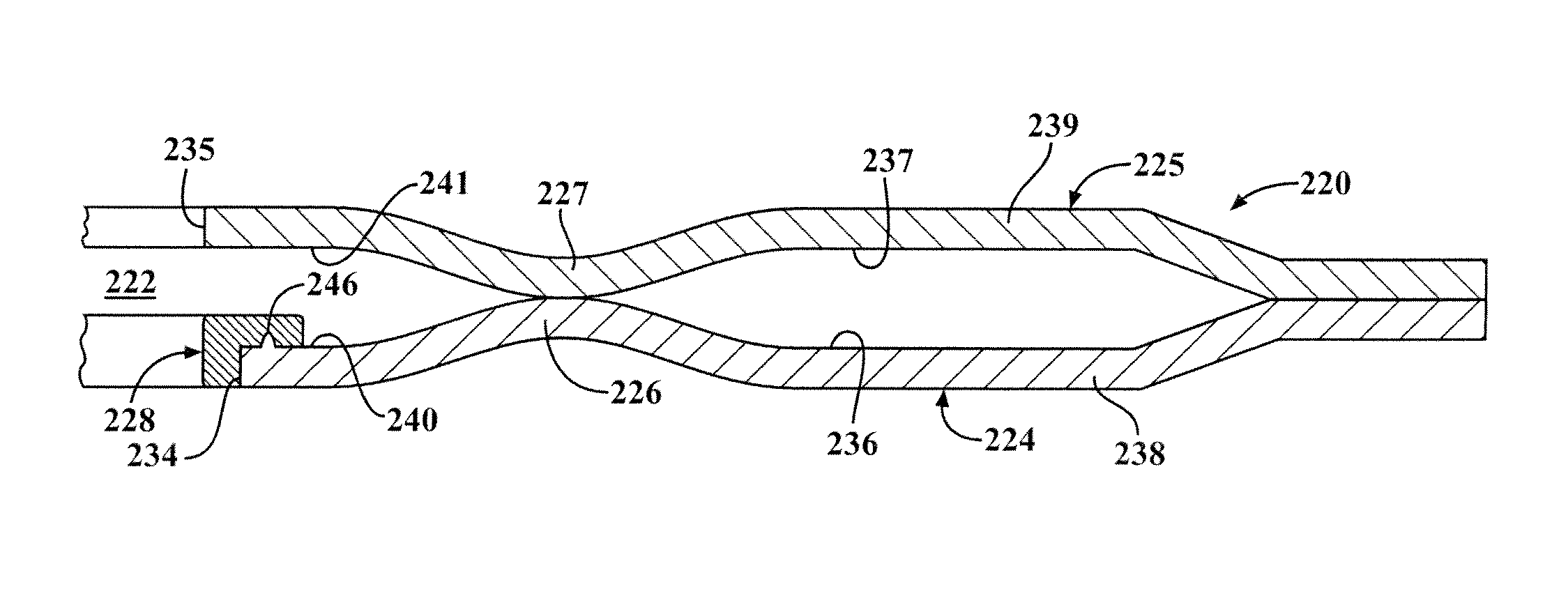
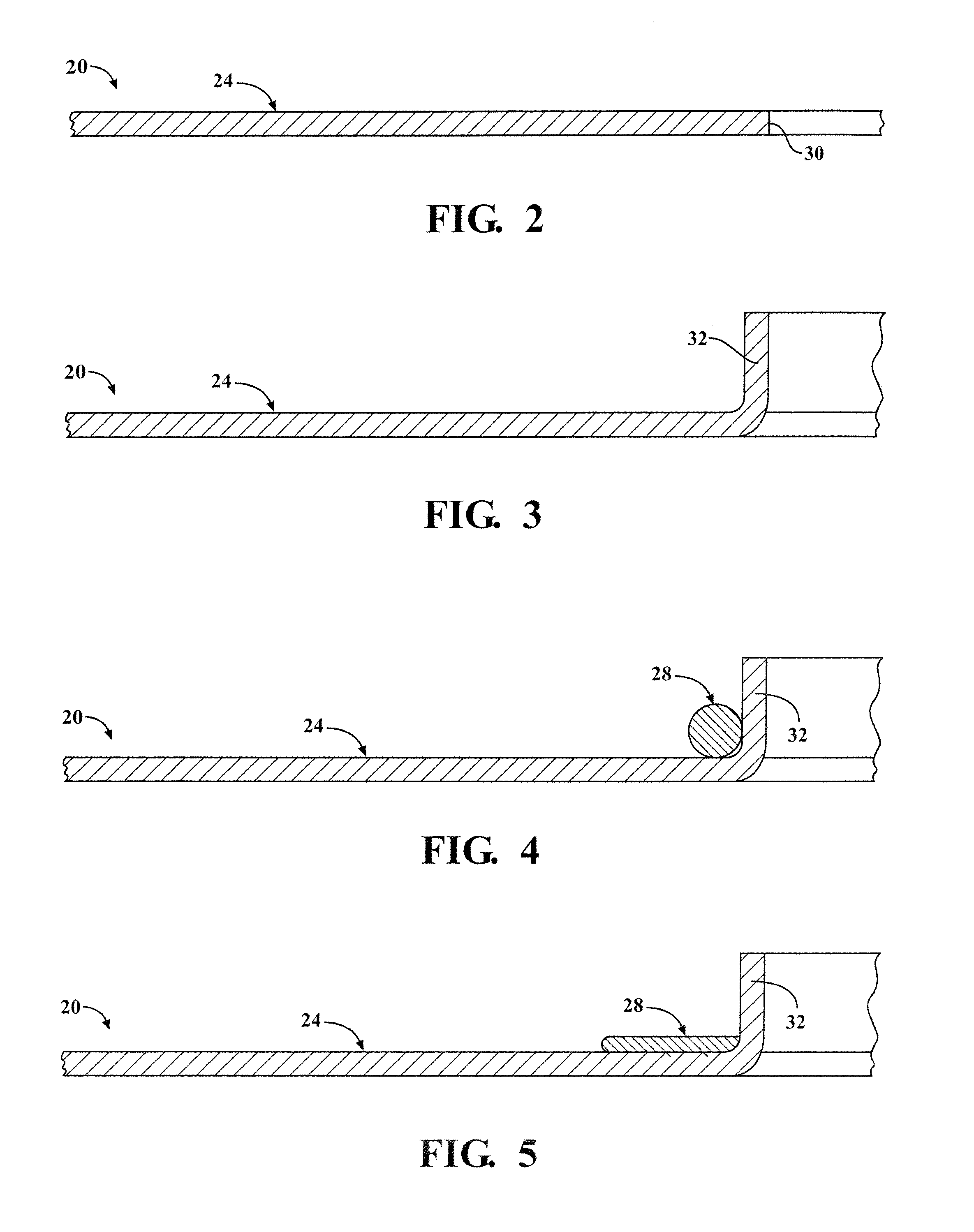
[0032]Referring to the Figures, wherein like numerals indicate corresponding parts throughout the several views, a gasket 20 constructed according to one aspect of the present invention and configured for establishing a seal between a cylinder head (not shown) and an engine block (not shown) is illustrated in cross-section in FIG. 8. The gasket 20 includes at least one circular opening 22 surrounding at least one cylinder bore opening in the engine block, as will be appreciated by those of skill in the art. The gasket 20 includes a functional layer 24 having a compression bead 26 spaced radially from the opening 22 for elastically deforming to establish the seal between the cylinder head and the engine block. As will be discussed in further detail below, the gasket 20 also has a compression limiter 28 disposed between the opening 22 and the compression bead 26 for preventing the compression bead 26 from being fully flattened between the cylinder head and the engine block. Although t...


PUM

PropertyMeasurementUnit
widthaaaaaaaaaa
thicknessaaaaaaaaaa
diameteraaaaaaaaaa

Abstract

A static gasket configured for establishing a seal between a cylinder head and an engine block including at least one layer having an opening and at least one compression bead. The compression bead extends circumferentially about the opening and projects out of a plane for deforming elastically when the gasket is compressed between the cylinder head and the engine block. A compression limiter which is formed from a metal wire is disposed radially between the opening and the compression bead for preventing the compression bead from being fully flattened, even if the cylinder head is overloaded onto the engine block. The compression bead is preferably induction and / or resistance welded to at least one of the layer(s).

Description

BACKGROUND OF THE INVENTION[0001]1. Field of the Invention[0002]The invention relates generally to static gaskets of the type used to establish a gas-tight seal between two members to be clamped together, and more particularly to static gaskets such as cylinder head gaskets.[0003]2. Related Art[0004]In establishing a gas-tight seal between two members to be clamped together, such as a cylinder head and an engine block, it is common to use a static cylinder head gasket having one or more layers. Generally, at least one of the layer(s), sometimes referred to as a functional layer, has a compression bead to establish the fluid tight seal. The gasket may also include at least one distance layer, which may be configured to backload stoppers and limit the compression of the compression bead, thereby improving fatigue resistance. Unfortunately, while fastening the cylinder head to the engine block, the compression bead can be over-compressed and substantially flattened. If the compression ...

Claims


Application Information

Patent Timeline
Patent Type & Authority Applications(United States)
IPC IPC(8): F02F11/00B23P15/00
CPCF16J15/0825Y10T29/49297F16J2015/0862F02F11/002
Inventor SWASEY, THOMAS
Owner FEDERAL MOGUL MOTORPARTS LLC
Learn More