High throughput physical vapor deposition apparatus and method for manufacture of solid state batteries

Inactive Publication Date: 2013-08-29
SAKTI3
View PDF21 Cites 5 Cited by
  • Summary
  • Abstract
  • Description
  • Claims
  • Application Information

AI Technical Summary

Benefits of technology

The present invention has addressed the problem of supplying enough deposition material to the evaporation source to deposit suitable films of significant thickness on large areas without changes in deposition conditions, rates, or quality. By taking learning from the chemical industries use of hot wall reactors, and decreasing the time the material to be deposited is subjected to heat, while increasing the surface to volume ratio of the evaporant, it has proven possible to reduce the residual non-stochiometric and non-vaporizable portion of the starting material by over 80%. Also, by carefully controlling the temperature of the evaporation surface, it is possible to significantly increase the rate of deposition without the detrimental process conditions seen with current technology. Further, since the evaporant time at temperature has been limited to the sub-second range, it is possible to supply a constant flow of these high surface-to-volume ratio materials from a central reservoir essentially providing a fresh source of evaporant material uncontaminated by heating. Finally, to allow long runs, now possible by this invention, it has been shown that the deposition material reservoir may be provided with the proper valves and fittings to allow refilling from outside of the vacuum tool without stopping the processing inside of the tool.

Problems solved by technology

It is well known that complex metal oxides can be suitable for solid state lithium ion batteries, however; it is also known that these same materials, for the most part, cannot be economically vacuum deposited for a number of fundamental reasons.
First is that they, like all alloys and complex compounds, have components that will evaporate at different rates due to different elemental vapor pressures, leading to a significant change between the starting material and the deposited film.
Additionally, many of these compounds degrade or decompose (e.g., become something that does not evaporate, changes oxide state or crystal phase, or otherwise becomes less desirable for the stated purpose) upon heating below their vapor pressure, even in very low vacuum environments.
Decomposition will also lead to unwanted deposited film stochiometery and will significantly reduce the amount of starting material that can be successfully deposited.
This leads to large amounts of waste remaining in the deposition source changing and hindering further deposition.
High rates ate also limited because simply increasing the area of evaporant or evaporation temperature also increases these issues.
Simply using large pots, containers, etc. of these materials only exacerbate these problems.

Method used


Image

  • High throughput physical vapor deposition apparatus and method for manufacture of solid state batteries
  • High throughput physical vapor deposition apparatus and method for manufacture of solid state batteries
  • High throughput physical vapor deposition apparatus and method for manufacture of solid state batteries

Examples


Embodiment Construction

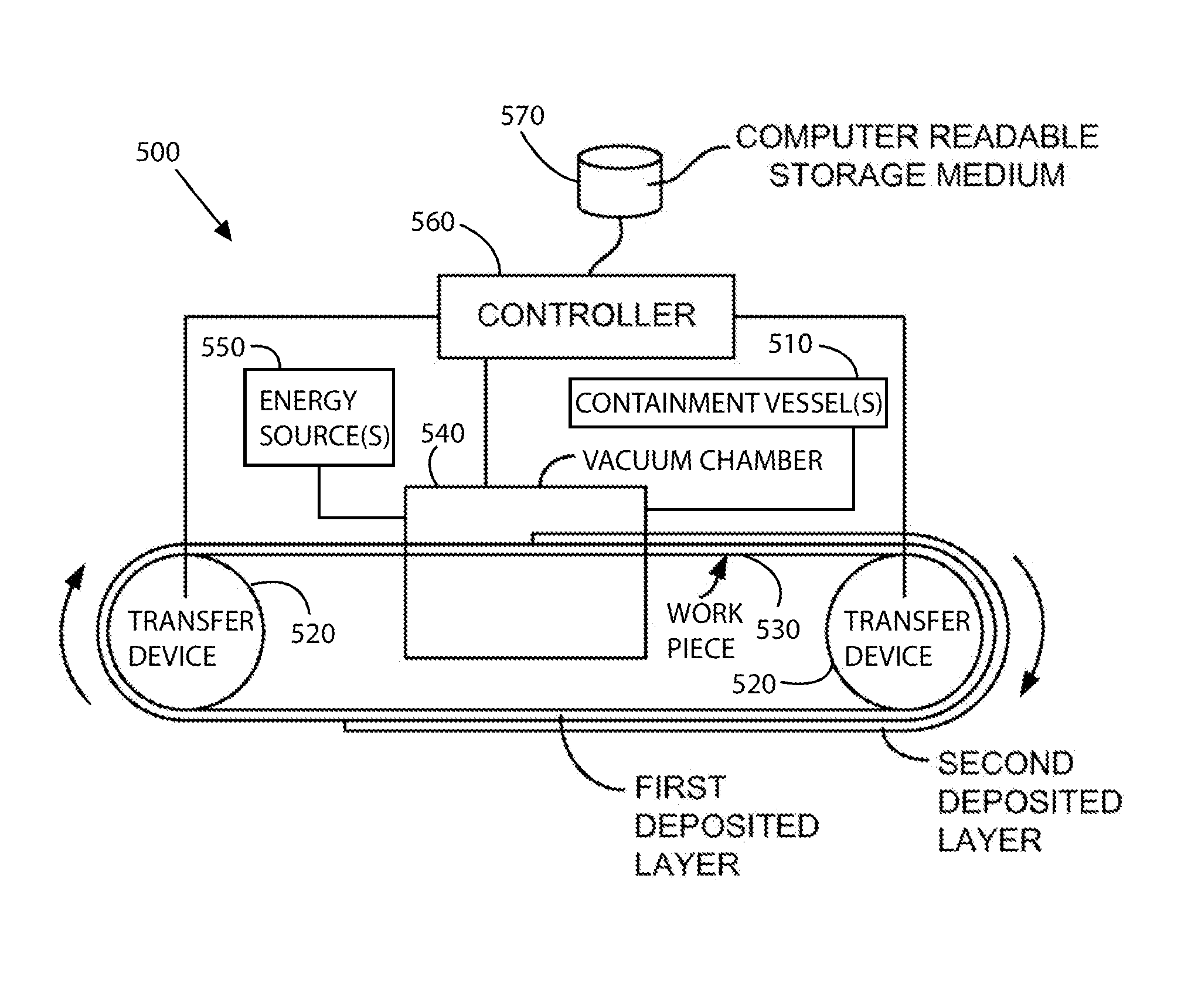
[0033]According to the present invention, apparatus related to manufacture of electrochemical cells are provided. More particularly, the present invention provides an apparatus and method of manufacturing a solid state thin film battery device. Merely by way of example, the invention has been provided with use of lithium based cells, but it would be recognized that other materials described above, could be designed in the same or like fashion. Additionally, such batteries can be used for a variety of applications such as portable electronics (cell phones, personal digital assistants, music players, video cameras, and the like), power tools, power supplies for military use (communications, lighting, imaging and the like), power supplies for aerospace applications (power for satellites), and power supplies for vehicle applications (hybrid electric vehicles, plug-in hybrid electric vehicles, and fully electric vehicles). The design of such batteries is also applicable to eases in which...


PUM

PropertyMeasurementUnit
Lengthaaaaaaaaaa
Lengthaaaaaaaaaa
Fractionaaaaaaaaaa

Abstract

An apparatus for formation of element(s) of an electrochemical cell using a complete process. The apparatus includes a first work piece configured to a transfer device, a source of material in fluid form, a reaction region operably coupled to the source of material and a second work piece configured within a distance of the reaction region. The apparatus also has an energy source configured to the reaction region to subject a portion of the material to energy to substantially evaporate the portion of the material within a time period and cause deposition of a gaseous species derived from the evaporated material onto a surface region of the second work piece to form a thickness of material for a component of the solid state electrochemical device and a vacuum chamber to maintain at least the first and second work pieces, the reaction region, and the material within a vacuum environment.

Description

CROSS-REFERENCES TO RELATED APPLICATIONS[0001]The present application is a continuation-in-part of U.S. patent application Ser. No. 13 / 292,368, filed Nov. 9, 2011, and titled HIGH THROUGHPUT PHYSICAL VAPOR DEPOSITION APPARATUS AND METHOD FOR MANUFACTURE OF SOLID STATE BATTERIES, commonly assigned. The present application also incorporates by reference, for all purposes, the following pending patent application: U.S. patent application Ser. No. 12 / 484,966, filed Jun. 15, 2009, and titled METHOD FOR HIGH VOLUME MANUFACTURE OF ELECTROCHEMICAL CELLS USING PHYSICAL VAPOR DEPOSITION, commonly assigned; and U.S. patent application Ser. No. 12 / 484,959 filed Jun. 15, 2009, titled COMPUTATIONAL METHOD FOR DESIGN AND MANUFACTURE OF ELECTROCHEMICAL SYSTEMS, commonly assigned.BACKGROUND OF THE INVENTION[0002]This present invention relates to manufacture of electrochemical cells. More particularly, the present invention provides an apparatus and method for manufacturing a solid state thin film ba...

Claims


Application Information

Patent Timeline
IPC IPC(8): H01M4/04
CPCH01M4/0423Y02T10/7011C23C14/246H01M4/04H01M2008/1095H01M4/0407H01M10/0472H01M10/052H01M4/0402Y02E60/10Y02E60/50
Inventor KIM, HYONCHEOLLANGLOIS, MARCCHUNG, MYOUNGDOSASTRY, ANN MARIE
Owner SAKTI3
Why Eureka
Try Eureka