Transmission system and electronic equipment

a transmission system and electronic equipment technology, applied in the field of transmission systems and electronic devices, can solve the problems of difficult estimation of the generation of em the inability to completely prevent emi in principle, and the inability to generate emi at a design stage, so as to reduce the frequency of generating block noise on the screen, and reduce the probability of occurrence of the peak value of emi

Inactive Publication Date: 2013-08-22
ORMON CORP
View PDF4 Cites 10 Cited by
  • Summary
  • Abstract
  • Description
  • Claims
  • Application Information

AI Technical Summary

Benefits of technology

[0043]According to the configuration, in the case that the EMI is generated in the electronic device, the probability of occurrence of the peak value of the EMI can be decreased. In the case that the electronic device is a mobile phone, the frequency of generating a sound skip during phone call can be decreased. In the case that the electronic device is a mobile television set or a television telephone, the frequency of generating a block noise on a screen can be decreased.
[0044]According to at least one embodiment of the present invention, the probability of occurrence of the peak value of the EMI can be decreased in the serial interface, which takes at least two different voltage values and transmits the signals at different transmission speeds with the voltage values.

Problems solved by technology

On the other hand, with enhancing operating frequency of an information processing device, an electromagnetic noise (hereinafter also referred to as EMI) generated from an inside of the information processing device, particularly a data transmission line becomes a problem.
Because the methods disclosed in Patent Documents 1 and 2 are methods for bringing the two transmission lines close to each other, the EMI cannot completely be prevented in principle.
Additionally, the EMI is also generated by various causes, such as a board environment, a variation in production, and time-related degradation.
Accordingly, it is difficult to estimate the generation of the EMI at a design stage.
For example, in the case that the shield is placed on a display surface, possibly visibility cannot be ensured.
In the case that the shield is placed on the wiring, possibly a bending property of the wiring cannot be ensured.
Accordingly, unfortunately the device vulnerable to the EMI cannot be placed around a region where the shield is hardly placed.
However, unfortunately the EMI including the harmonic component is easily generated during the transition between the voltage states.
When the probability of occurrence of the peak value of the EMI is increased, the EMI has the influence on the electronic device, which results in a problem in that, for example, a noise component is included in a radio signal received by the antenna of the electronic device.
Therefore, for example, there is a possibility of generating the sound skip during the phone call of the mobile phone or a block noise on the screen of a mobile television set or a television telephone.
The noise including the harmonic component is easily generated when the transition of the voltage state is generated.

Method used


Image

  • Transmission system and electronic equipment
  • Transmission system and electronic equipment
  • Transmission system and electronic equipment

Examples


first embodiment

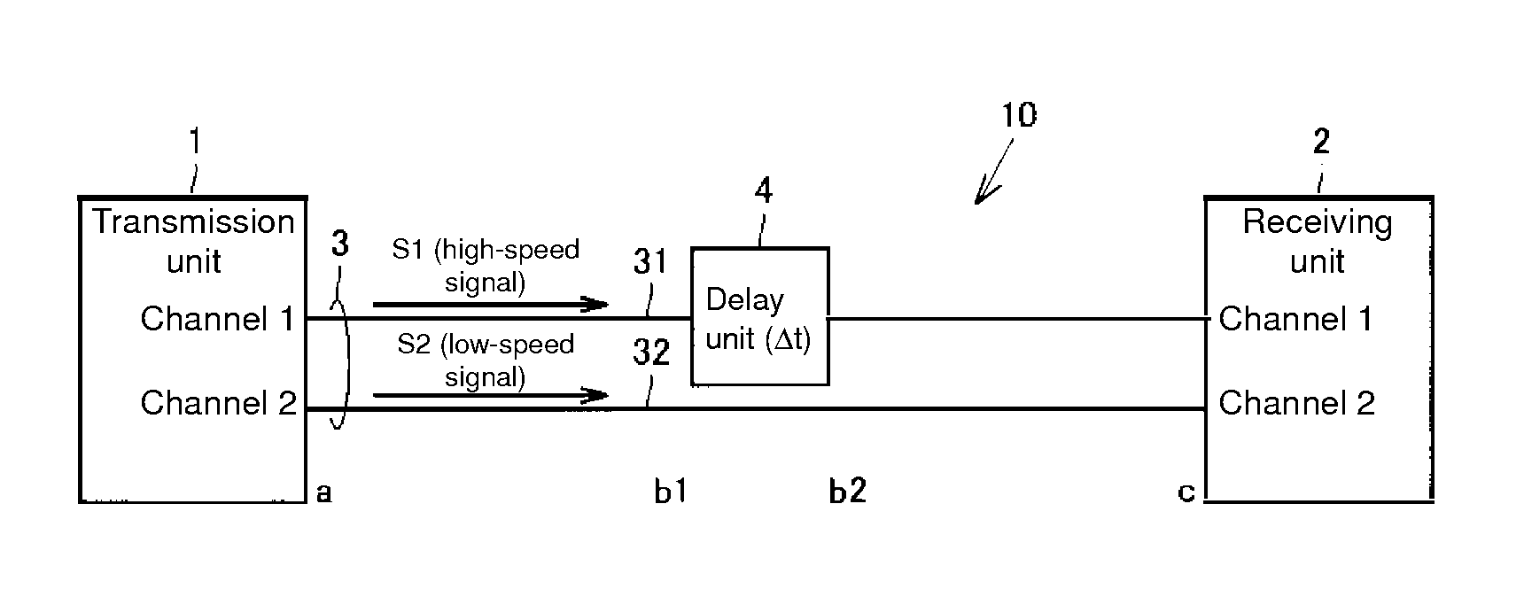
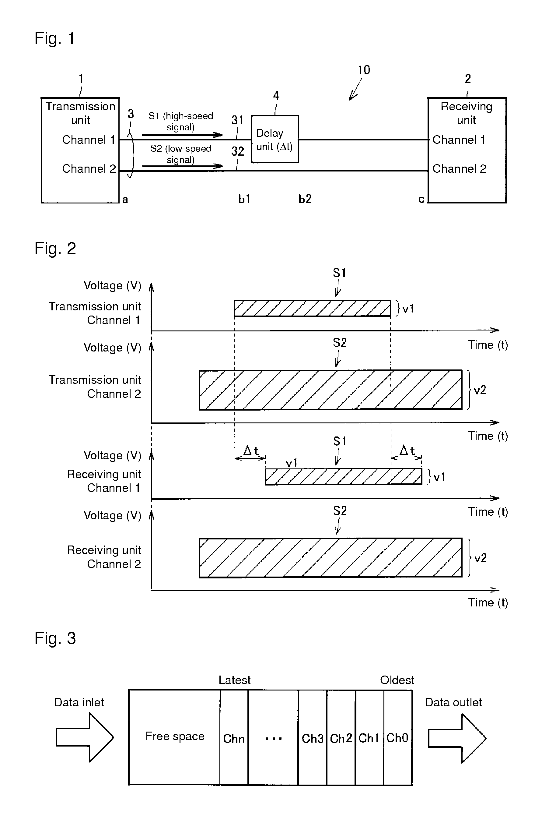
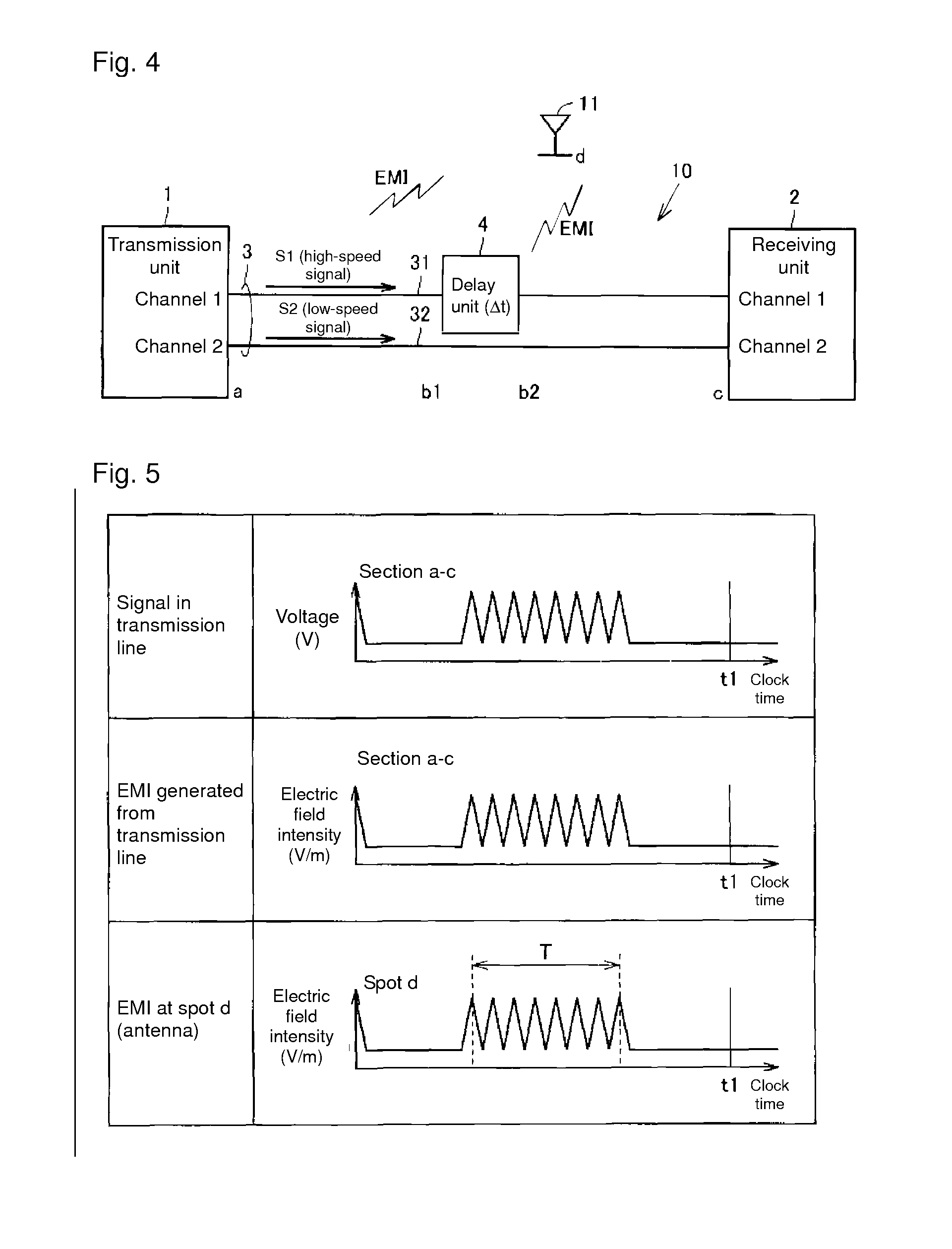
[0074]FIG. 1 is a view illustrating a configuration of a transmission system according to a first embodiment of the present invention. Referring to FIG. 1, a transmission system 10 includes a transmission unit 1, a receiving unit 2, a transmission line 3, and a delay unit 4.

[0075]The transmission system according to an embodiment of the present invention can be applied to a serial interface, which takes at least two different voltage values and transmits a signal at a different transmission speed with each voltage value.

[0076]The transmission unit 1 includes a channel 1 through which a high-speed signal S1 is transmitted and a channel 2 through which a low-speed signal S2 is transmitted. Similarly, the receiving unit 2 includes a channel 1 through which the high-speed signal S1 is transmitted and a channel 2 through which the low-speed signal S2 is transmitted.

[0077]The transmission line 3 includes a transmission line 31 through which the high-speed signal S1 is transmitted and a tr...

second embodiment

[0096]A whole configuration of a transmission system according to a second embodiment is identical to that in FIG. 1. As illustrated in FIG. 9, the transmission unit 1 and the receiving unit 2 include PLL circuits 1a and 2a, respectively. The PLL circuit 1a is used to determine the transmission speed (in a transmission frequency band) of the signal of the transmission unit 1. Similarly the PLL circuit 2a is used to determine the transmission speed of the signal of the receiving unit 2.

[0097]In the second embodiment, the high-speed signal includes a valid signal to processing (for example, image display processing) based on the high-speed signal and an invalid signal to the processing. The transmission system of the second embodiment delays only the valid signal of the invalid signal and the valid signal.

[0098]FIG. 10 is a timing chart illustrating the high-speed signal transmission and the low-speed signal transmission, which are performed by the transmission system of the second em...

third embodiment

[0109]A transmission system according to a third embodiment differs from the transmission system of the first embodiment in the configuration of the transmission line.

[0110]FIG. 13 is a view illustrating a configuration of a transmission system 10A of the third embodiment. Referring to FIGS. 1 and 13, the transmission system 10A differs from the transmission system 10 in that a signal separator 5 and a signal coupler 6 are provided on the transmission line 3. Transmission lines 33 and 34 are provided in parallel between the signal separator 5 and the signal coupler 6. The delay unit 4 is provided on the transmission line 33.

[0111]The transmission unit 1 transmits the high-speed signal S1 and the low-speed signal S2 through the transmission line 3 using the same channel (in this case, the channel 1). The signal separator 5 separates the high-speed signal S1 and the low-speed signal S2, which are transmitted from the transmission unit 1 through the transmission line 3. There is no par...


PUM


Abstract

A data transmission system is provided with a transmission unit, a receiving unit, transmission paths, and a delay unit. The delay unit is disposed on a transmission path along which a high-speed signal is transmitted, and delays the transmission of the high-speed signal with respect to a low-speed signal. When the high-speed signal is transmitted from a section b2 to c along the transmission path, a delay time of Δt occurs with respect to when the high-speed signal is transmitted from a section a to b1 along the transmission path. In other words, the phase of the high-speed signal transmitted from section b2 to c is shifted with respect to the phase of the high-speed signal transmitted from section a to b1. Consequently, a time interval in which an EMI peak value occurs can be reduced, thereby enabling the probability of an EMI peak value occurring to be reduced.

Description

BACKGROUND OF THE INVENTION[0001]1. Technical Field[0002]The present invention relates to a transmission system and an electronic device equipped therewith, particularly to a technology for a countermeasure to electromagnetic interference (EMI) of the electronic device.[0003]2. Background Art[0004]An operating frequency of an information processing device typified by a mobile phone is enhanced year by year with the progress of high integration or high functionality of a semiconductor element. Therefore, there is increasing use of a serial differential interface that can transmit a signal at high speed. For example, spread of interfaces using an MIPI D-PHY layer such as MIPI (Mobile Industry Processor Interface) DSI and CSI2 accelerates. In such interfaces, through the same transmission line, differential transmission of high-speed signals, such as an image data signal, is performed with a low voltage and non-differential transmission of low-speed signals, such as a control signal, i...

Claims


Application Information

Patent Timeline
Patent Type & Authority Applications(United States)
IPC IPC(8): H04B10/2507H04B1/3822H04B1/40
CPCH04B15/04H04B10/2507H04L25/14
Inventor ISHIDA, YOSHIHISAYASUDA, NARUHOSOKAWA, HAYAMI
Owner ORMON CORP
Why Eureka
Try Eureka