
Active chilled beam with sterilization means

Inactive Publication Date: 2013-08-22
MESTEK
View PDF15 Cites 6 Cited by
  • Summary
  • Abstract
  • Description
  • Claims
  • Application Information

AI Technical Summary

Benefits of technology

The present invention is related to an air-handling unit that includes a primary air plenum and a primary air inlet for providing primary air to the plenum. The unit also includes an irradiate cavity with a secondary air inlet for receiving secondary air, and a sterilization mechanism positioned in the irradiate cavity for effectively treating and sterilizing the secondary air. The technical effect of the invention is to increase the time the air stays in the mixing chamber / plenum and minimize the leakage of sterilizing light.

Problems solved by technology

Known active chilled beam systems, however, are not particularly suitable for hospitals and other environments wherein recirculated or secondary air may carry bacteria, germs, and the like.

Method used


Image

  • Active chilled beam with sterilization means
  • Active chilled beam with sterilization means
  • Active chilled beam with sterilization means

Examples


Embodiment Construction

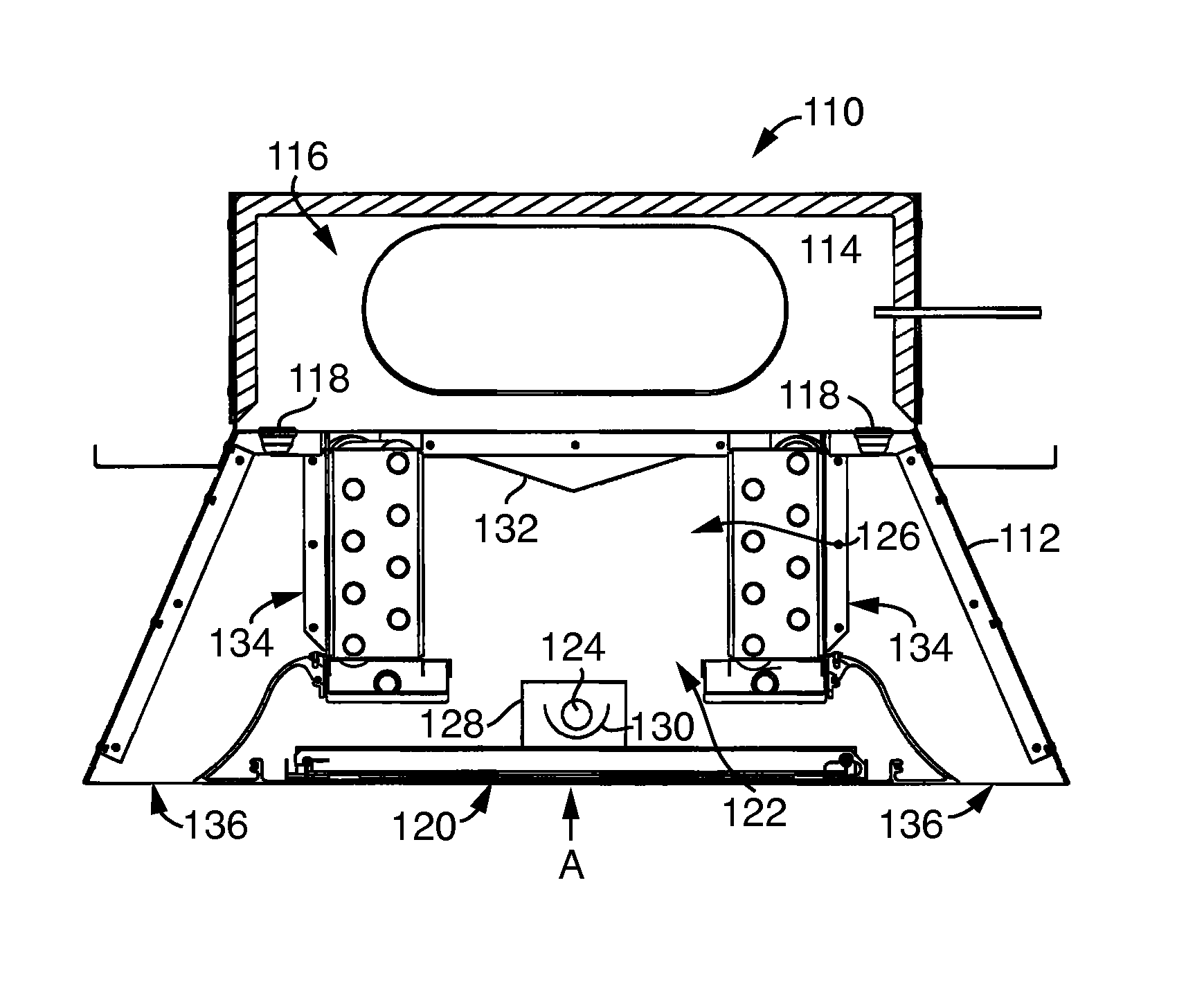
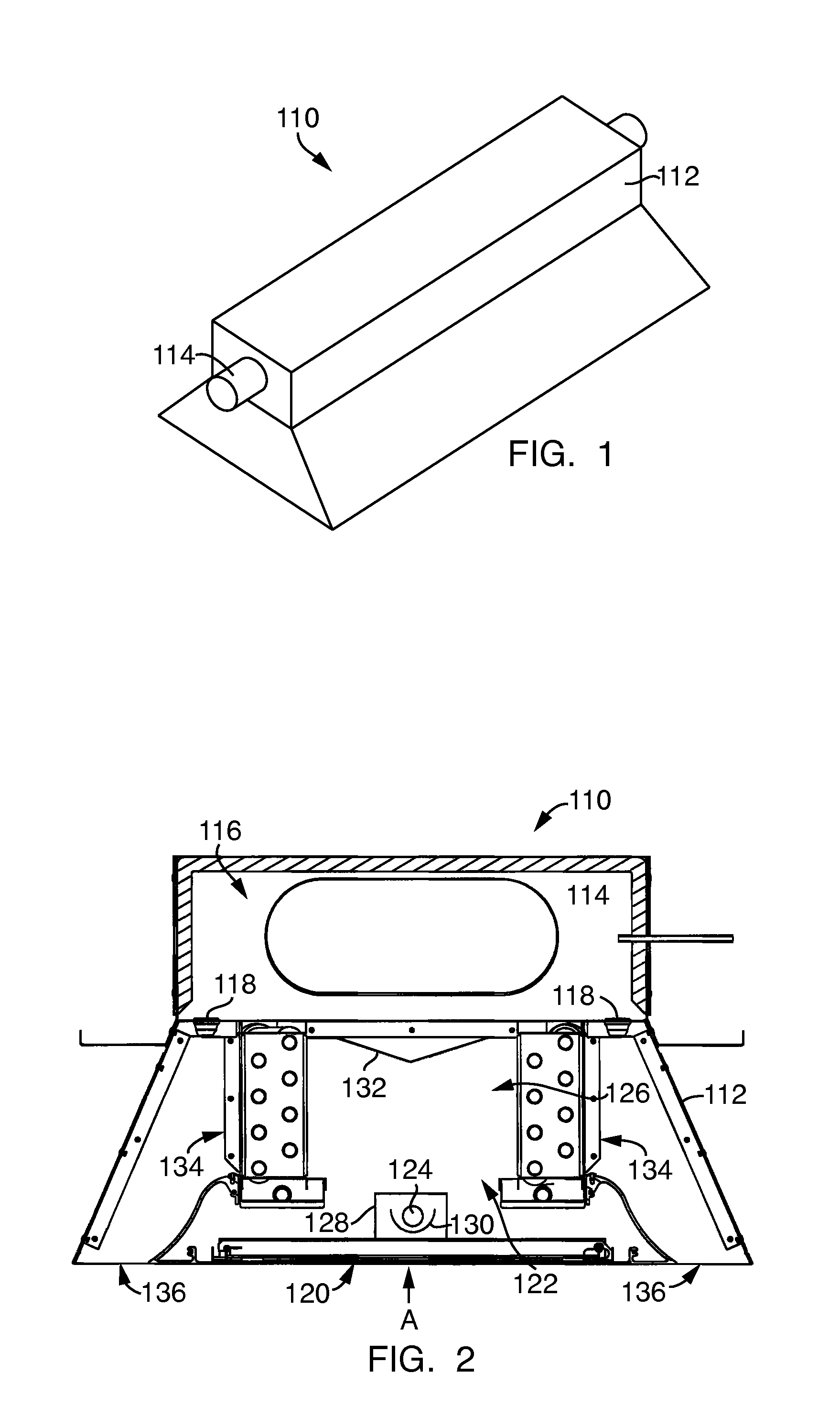
[0022]Referring to FIGS. 1 and 2, an active chilled beam 110 according to an embodiment of the present invention is shown. As shown therein, the active chilled beam 110 generally takes the form of a chamber 112 having a primary air inlet 114. The chamber 112 is generally of a sheet metal construction and is provided with flanges for mounting the chilled beam 110 to a ceiling or other support structure. Alternatively, the chamber 112 may be constructed from other materials such as sandwich-foam sheets or fiber reinforced plastics.

[0023]With specific reference to FIG. 2, primary / ventilation air from a central air handling system (not shown for clarity) is supplied through the primary air inlet 114 to a primary air plenum 116 in the chamber 112. The primary air within the air plenum 116 is pressurized as compared to a secondary / recirculated air from the room. As a result, the pressurized primary air from the primary air plenum 116 is directed downward through rows of induction nozzles ...


PUM


Abstract

An air-handling unit includes a primary air plenum and a primary air inlet in fluid communication with the primary air plenum. The primary air inlet is configured to provide a flow of primary air to the primary air plenum. The air-handling unit also includes a chamber in fluid communication with the primary air plenum. The chamber includes an irradiate cavity and a secondary air inlet configured to accept a flow of secondary air into the irradiate cavity, and a sterilization mechanism positioned in the irradiate cavity. The sterilization mechanism is configured to effectively treat and sterilize the secondary air.

Description

CROSS-REFERENCE TO RELATED APPLICATIONS[0001]This application claims the benefit of U.S. Provisional Application Ser. No. 61 / 594,528, filed on Feb. 3, 2012, and U.S. Provisional Application Ser. No. 61 / 639,169, filed on Apr. 27, 2012, both of which are herein incorporated by reference in their entireties.FIELD OF THE INVENTION[0002]The present invention relates generally to an induction air handling unit and, more particularly, to an active chilled beam with air sterilization means.BACKGROUND OF THE INVENTION[0003]Known air-conditioning systems treat predominately outside air that is mixed with a proportion of return or recirculated air from within a building. This conditioned air is then used to meet the heating or cooling load within a particular space, such as a number of rooms on a floor or an open space area on a floor of a building.[0004]A chilled beam is one such type of convection HVAC system designed to heat or cool buildings. Pipes carrying water are passed through a beam;...

Claims


Application Information

Patent Timeline
IPC IPC(8): F24F3/16F24F1/0047F24F8/22F24F1/0063F24F1/0076
CPCF24F1/0007F24F3/16F24F2003/1667F24F2001/0037F24F1/0047Y02A50/20F24F8/22F24F1/0076F24F1/0063
Inventor PETROVIC, VLADIMIR M.HARRIS, DANIELSHUKLA, RAINY
Owner MESTEK
Learn More