
Amplifier circuit and operating method thereof

Inactive Publication Date: 2013-08-15
SAMSUNG ELECTRO MECHANICS CO LTD
View PDF3 Cites 0 Cited by
  • Summary
  • Abstract
  • Description
  • Claims
  • Application Information

AI Technical Summary

Benefits of technology

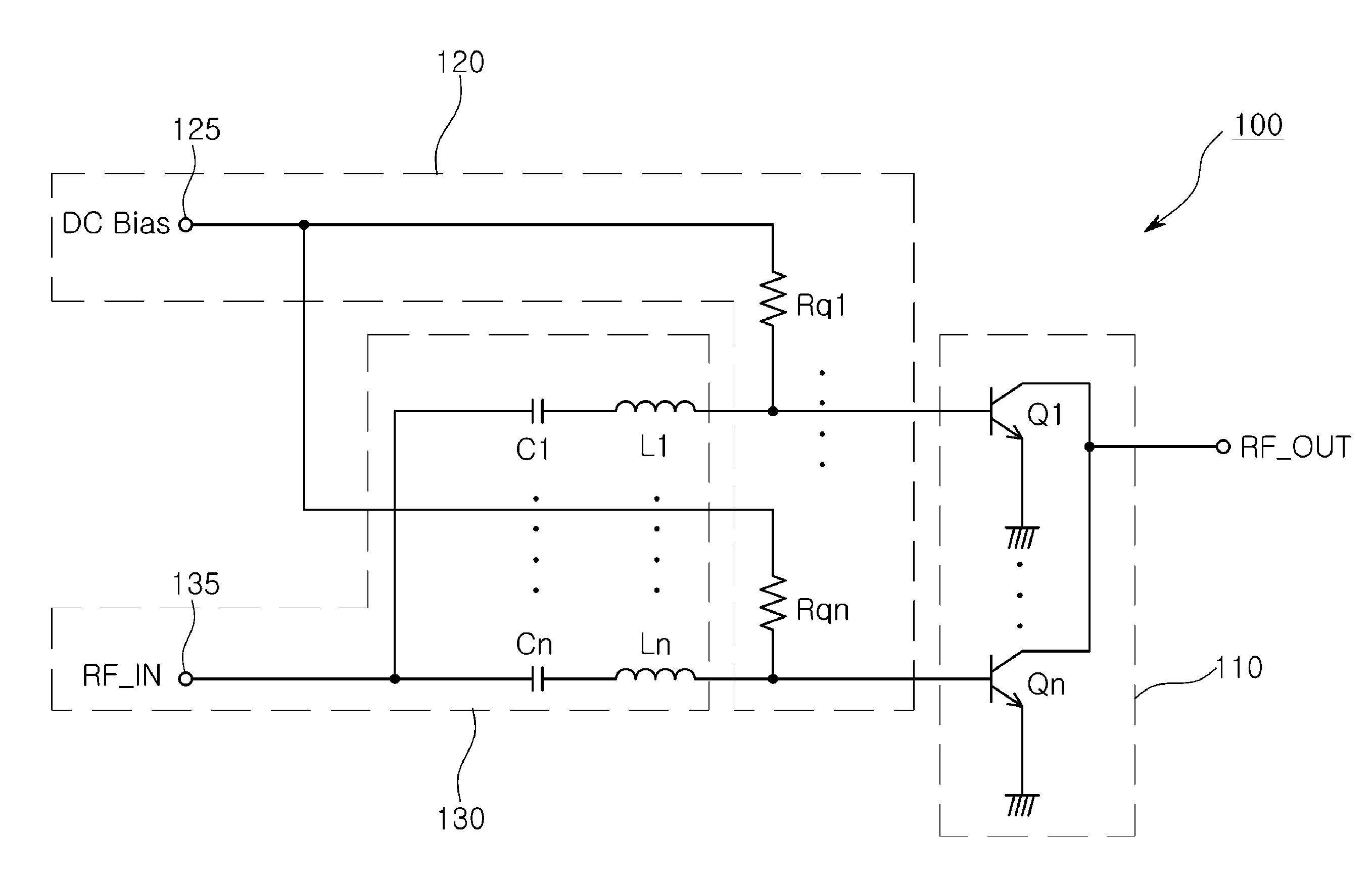
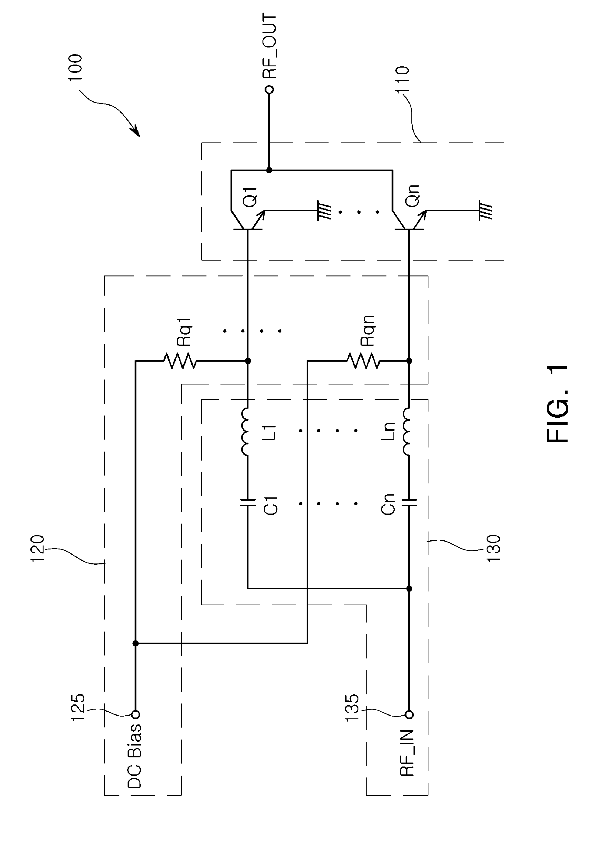
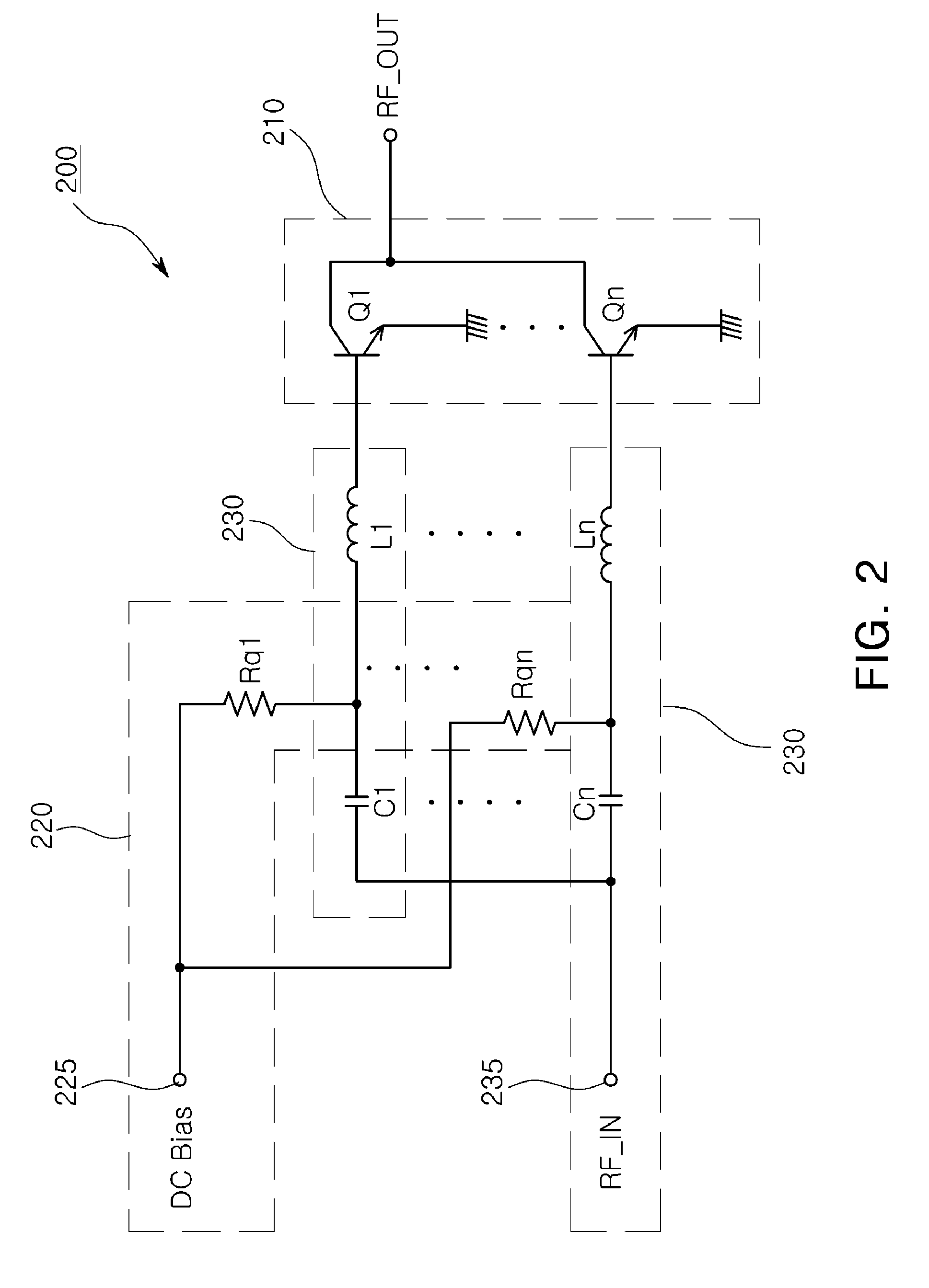
This patent is about an amplifier circuit that prevents a transistor from overheating and causing damage. It does this by adding a resistor in the direct current bias signal path and using an inductive element and capacitive element in the input signal path. This circuit also suppresses oscillations and removes harmonic components from the input signal.

Problems solved by technology

In the case in which the generated heat is not efficiently controlled, a thermal runaway phenomenon may occur, deteriorating the performance of, or even destroying, the amplifier element.
The thermal runaway phenomenon may be a serious problem, particularly in an amplifier circuit including a plurality of transistors.
However, since only a capacitor and a resistor are connected to a signal input terminal RF_IN through which a wireless signal to be amplified is input, and the base terminal of the plurality of transistors, an effect of suppressing oscillations or transmitting only a signal having a specific frequency band may not be expected.

Method used


Image

  • Amplifier circuit and operating method thereof
  • Amplifier circuit and operating method thereof
  • Amplifier circuit and operating method thereof

Examples


Embodiment Construction

[0034]Embodiments of the present invention will be described in detail with reference to the accompanying drawings. These embodiments will be described in detail in order to allow those skilled in the art to practice the present invention. It should be appreciated that various embodiments of the present invention are different but are not necessarily exclusive. For example, specific shapes, configurations, and characteristics described in an embodiment of the present invention may be implemented in another embodiment without departing from the spirit and scope of the present invention. In addition, it should be understood that the positions and arrangements of individual components in each embodiment may be changed without departing from the spirit and scope of the present invention. Therefore, the detailed description provided below should not be construed as being restrictive. In addition, the scope of the present invention is defined only by the accompanying claims and their equi...


PUM


Abstract

There is provided an amplifier circuit. The amplifier circuit includes an amplifying unit including at least one transistor; at least one first bias circuit unit including a resistor and connected to the at least one transistor; and at least one second bias circuit unit connected between an input terminal to which an input signal is applied and the at least one transistor so as to block an input signal having a frequency higher than a first frequency or having a frequency lower than a second frequency. The amplifier circuit according to embodiment of the present invention may prevent thermal runaway, remove a harmonic component from an input signal to be amplified and suppress oscillations.

Description

CROSS-REFERENCE TO RELATED APPLICATIONS[0001]This application claims the priority of Korean Patent Application No. 10-2012-0013141 filed on Feb. 9, 2012, in the Korean Intellectual Property Office, the disclosure of which is incorporated herein by reference.BACKGROUND OF THE INVENTION[0002]1. Field of the Invention[0003]The present invention relates to an amplifier circuit including a transistor, and more particularly, to an amplifier circuit capable of preventing thermal runaway and optimizing response characteristics in a frequency band to suppress oscillations and remove harmonic components.[0004]2. Description of the Related Art[0005]An amplifier circuit, a circuit amplifying an input signal to generate an output signal, is widely used in electronic device power supply systems as well as in amplifying a communication signal of a wireless communication device. An amplifier circuit may include a bias circuit applying a bias signal for operating the amplifier circuit in a voltage o...

Claims


Application Information

Patent Timeline
IPC IPC(8): H03F3/04
CPCH03F2200/18H03F2200/225H03F3/211H03F1/32H03F3/19H03F1/08H03F1/26H03F1/30
Inventor SONG, YOUNG JEANWON, JUN GOOKIM, YOUN SUKIIZUKA, SHINICHIPARK, JU YOUNGKIM, KI JOONG
Owner SAMSUNG ELECTRO MECHANICS CO LTD
Learn More