Method for controlling an inverter

a technology of inverter and control method, which is applied in the direction of motor/generator/converter stopper, dynamo-electric converter control, dc-ac conversion without reversal, etc., can solve the problem that output optimization is impossible at less than the rated speed, and achieve the effect of enhancing work efficiency

Active Publication Date: 2013-08-15
LSIS CO LTD
View PDF2 Cites 17 Cited by
  • Summary
  • Abstract
  • Description
  • Claims
  • Application Information

AI Technical Summary

Benefits of technology

[0017]Methods and systems consistent with the present disclosure provide a method for controlling an inverter configured to determine a maximum speed even at a scope less than a weak field operation area according to a load to thereby control the inverter at an optimal output.
[0027]The method for controlling an inverter according to exemplary embodiments of the present disclosure has an advantageous effect in that an output optimization is performed at a section over a rated speed, and an output optimization is also performed at a section less than a rated speed and at a speed level more than an optimal speed level defined by a user, whereby a motor can be driven at a maximum speed according to a load even at a section lower than a rated speed to thereby enhance a work efficiency.
[0028]Another advantageous effect is that a motor is driven on two references of a rated speed and an optimal speed level to thereby optimize a driving of the motor according to the motor and a load characteristic of the motor.

Problems solved by technology

However, referring to FIG. 2, this suffers from a disadvantage in that an optimal speed is determined through output optimization during an operation over a rated speed, and a predetermined speed is provided at an operation less than the rated speed, whereby the output optimization is impossible at the operation less than the rated speed.

Method used


Image

  • Method for controlling an inverter
  • Method for controlling an inverter
  • Method for controlling an inverter

Examples


Embodiment Construction

[0037]Features and advantages of the disclosed embodiments will be or will become apparent to one of ordinary skill in the art upon examination of the following figures and detailed description. It is intended that all such additional features and advantages be included within the scope of the disclosed embodiments, and protected by the accompanying drawings. Further, the illustrated figures are only exemplary and not intended to assert or imply any limitation with regard to the environment, architecture, or process in which different embodiments may be implemented. Accordingly, the described aspect is intended to embrace all such alterations, modifications, and variations that fall within the scope and novel idea of the present invention.

[0038]Hereinafter, a method for controlling an inverter according to exemplary embodiments of the present disclosure will be described in detail with reference to the accompanying drawings.

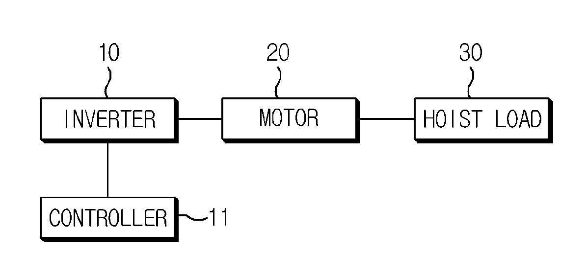
[0039]FIG. 3 is a structural view of an inverter system acc...


PUM


Abstract

Provided is a method for controlling an inverter, the method comprising calculating an optimal speed, determining a final speed as the optimal speed when a command speed is higher than a rated speed level of a motor, and determining the final speed as the command speed when the command speed is lower than or equal to the rated speed level, or higher than a predetermined optimal speed level.

Description

CROSS-REFERENCE TO RELATED APPLICATIONS[0001]Pursuant to 35 U.S.C. §119 (a), this application claims the benefit of earlier filing date and right of priority to Korean Patent Application No. 10-2012-0013864, filed on Feb. 10, 2012, the contents of which are hereby incorporated by reference herein in their entirety.BACKGROUND OF THE DISCLOSURE[0002]1. Field of Endeavor[0003]The present disclosure relates to a method for controlling an inverter.[0004]2. Background[0005]In general, a power inverter, or inverter, is an electrical power converter that changes DC (Direct Current) to AC (Alternating Current) at any required voltage and frequency through PWM (Pulse Width Modulation) switching operation by being connected to a three-phase commercial AC power source to generate a desired power and supplies the power to a motor, where the motor controlled by the inverter in turn generates a torque to drive a load.[0006]In general, a load applied by a motor-driving inverter system may be largel...

Claims


Application Information

Patent Timeline
Patent Type & Authority Applications(United States)
IPC IPC(8): H02P27/06H02M7/48H02P23/07H02P27/08
CPCH02P23/0086H02P27/06H02P21/0089
Inventor CHI, MIN HUN
Owner LSIS CO LTD
Why Eureka
Try Eureka