Alternating Parallel Fly Back Converter with Alternated Master-Slave Branch Circuits

a technology of master-slave branch circuit and converter, which is applied in the direction of power conversion system, electric variable regulation, instruments, etc., can solve the problems of mismatch between, aging of different devices, and affecting the efficiency of the conversion devi

Inactive Publication Date: 2013-08-08
ALTENERGY POWER SYST
View PDF5 Cites 21 Cited by
  • Summary
  • Abstract
  • Description
  • Claims
  • Application Information

AI Technical Summary

Benefits of technology

The invention provides an alternating parallel flyback converter with alternated master-slave branch circuits to increase the converter's reliability and service life. The converter has two flyback circuits: master and slave. The operation of each circuit is controlled by the current and voltage at the output terminal. The master branch circuit operates continuously, while the slave branch circuit only operates when power is higher than a certain threshold. The master and slave circuits can be alternated periodically, and the alternation can be done through the zero crossing of power. This helps to improve the converter's performance and reliability.

Problems solved by technology

However, all of the devices may consume more energy when two branch circuits operate simultaneously, whereby the efficiency may be decreased.
However, when the master branch circuit and the slave branch circuit are fixed, a mismatch between them and related problems (such as the temperature difference, aging of different devices, and the like) may be caused by different operation states between them.
In addition, the master branch circuit is a factor for limiting the reliability and service life of the converter because it operates more than the slave branch circuit.

Method used


Image

  • Alternating Parallel Fly Back Converter with Alternated Master-Slave Branch Circuits
  • Alternating Parallel Fly Back Converter with Alternated Master-Slave Branch Circuits
  • Alternating Parallel Fly Back Converter with Alternated Master-Slave Branch Circuits

Examples


Embodiment Construction

[0031]The invention will be further described by using the drawings and the embodiments.

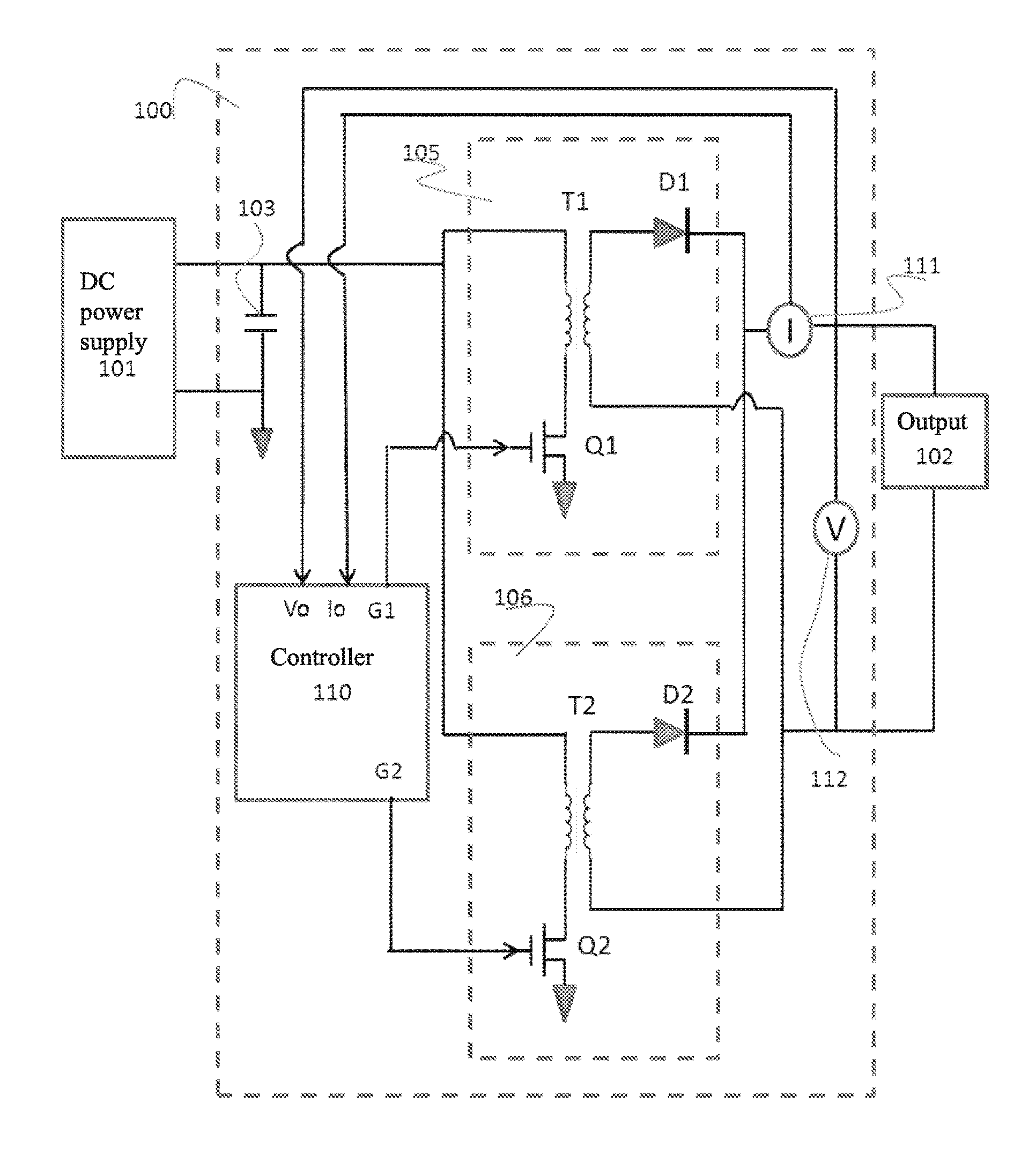
[0032]FIG. 1 shows a structure diagram of an embodiment of the alternating parallel flyback converter with alternated master-slave branch circuits of the invention. Referring to FIG. 1, for purpose of illustration, an example of two flyback circuits connected alternately in parallel are described in the embodiment, wherein one branch is defined as the master branch circuit, and the other branch is defined as the slave branch circuit, and wherein the embodiment is also a direct current to direct current (DC-DC) converter 100. The direct voltage of a direct power supply 101 is converted by the DC-DC converter 100 to a direct voltage output 102. The direct power supply 101 can be a photovoltaic DC power supply or a DC power supply of other source. The direct voltage output 102 can be connected to a device, which uses the DC power supply, including a direct current to alternating current (DC-AC) conv...


PUM


Abstract

An alternating parallel flyback converter with alternated master and slave circuit branches is provided. The flyback converter includes a master flyback circuit branch, a slave flyback circuit branch connected with the master flyback circuit branch in parallel, and a controller. The controller controls the operation of each of the flyback circuit branches based on the current and the voltage at the output terminal of the flyback converter. The master flyback circuit branch operates continuously while the slave flyback circuit branch only operates when the output power of the flyback converter is higher than a threshold. The master flyback circuit branch and the slave flyback circuit branch are periodically alternated, and in particular, through zero crossing of the power. With the flyback converter of the present invention, the reliability and the service life of the converter can be improved.

Description

CROSS REFERENCE TO RELATED APPLICATIONS[0001]This application is a National Phase application filed under 35 U.S.C. §371 of International Application No. PCT / CN2011 / 076541, filed Jun. 29, 2011, which claims benefit of and the priority to Chinese Patent Application No. CN 201010217523.3, filed Jul. 1, 2010, which applications are hereby incorporated by reference in their entirety.TECHNICAL FIELD[0002]The invention relates to an energy conversion device, particularly, an energy conversion device of flyback converter.BACKGROUND OF THE INVENTION[0003]A flyback conversion topology is a commonly used DC-DC conversion technology, and can be used in the condition where the electrical insulation, boosting and high efficiency are required. The flyback topology comprises a transformer, a switching device, and a diode. Normally, the switching device can be connected in series with the primary coil of the transformer, and the secondary coil of the transformer can be connected to the load via a s...

Claims


Application Information

Patent Timeline
IPC IPC(8): H02M3/335
CPCH02M3/33507H02M3/285
Inventor LUO, YUHAO
Owner ALTENERGY POWER SYST
Why Eureka
Try Eureka