Control apparatus for internal combustion engine

a control apparatus and internal combustion engine technology, applied in the direction of anti-theft devices, machines/engines, ignition safety means, etc., can solve the problems of high discharge voltage of spark plugs, no discharge sparks, and impair the reliability of spark plugs, so as to suppress the decrease of inductive voltage, suppress the decrease of electro-magnetic energy stored, and suppress the effect of reducing the voltage applied

Active Publication Date: 2013-08-08
DENSO CORP
View PDF22 Cites 13 Cited by
  • Summary
  • Abstract
  • Description
  • Claims
  • Application Information

AI Technical Summary

Benefits of technology

The present invention provides an ignition system that prevents the discharge voltage of the spark plug from becoming excessively high and also prevents the inductive voltage generated in the secondary coil from being lower than expected. This is achieved by providing a constant-voltage element in the constant-voltage path. Additionally, the invention includes a restricting element that blocks current flow when current is supplied to the primary coil, which helps determine the occurrence of an open failure in the constant-voltage path and prevents the decrease of the inductive voltage generated in the secondary coil, resulting in a reliable production of discharge sparks across the electrodes of the spark plug and avoiding an accidental fire in the engine.

Problems solved by technology

Thus, the spark plug will have high discharge voltage.
When the discharge voltage becomes high under the conditions where the electrodes' wear in the spark plug is advanced due to the increase of a running distance or the like, the discharge voltage may exceed an insulation-breakdown threshold voltage of a plug insulator at an early stage, impairing reliability of the spark plug.
As a result, discharge sparks would no longer be produced, which may lead to the occurrence of an accidental fire in the internal combustion engine.
As the duration of use of a spark plug becomes longer, the degree of deterioration of the spark plug becomes higher.
In this case, discharge sparks are no longer produced, leading to the occurrence of an accidental fire in the internal combustion engine.
For example, an open failure may occur in the constant-voltage element.
If an open failure occurs, the constant-voltage element loses its function of restricting the voltage applied to the gap.
This may impair the reliability of the ignition system including the spark plug.
In this case, for example, no discharge sparks are produced across the electrodes of the spark plug and thus an accidental fire may be caused in the engine.
However, from the viewpoint of determining the occurrence of an open failure in the constant-voltage path by the open failure judging means, the current that passes through the closed loop circuit when current is supplied to the primary coil cannot be blocked.

Method used


Image

  • Control apparatus for internal combustion engine
  • Control apparatus for internal combustion engine
  • Control apparatus for internal combustion engine

Examples


first embodiment

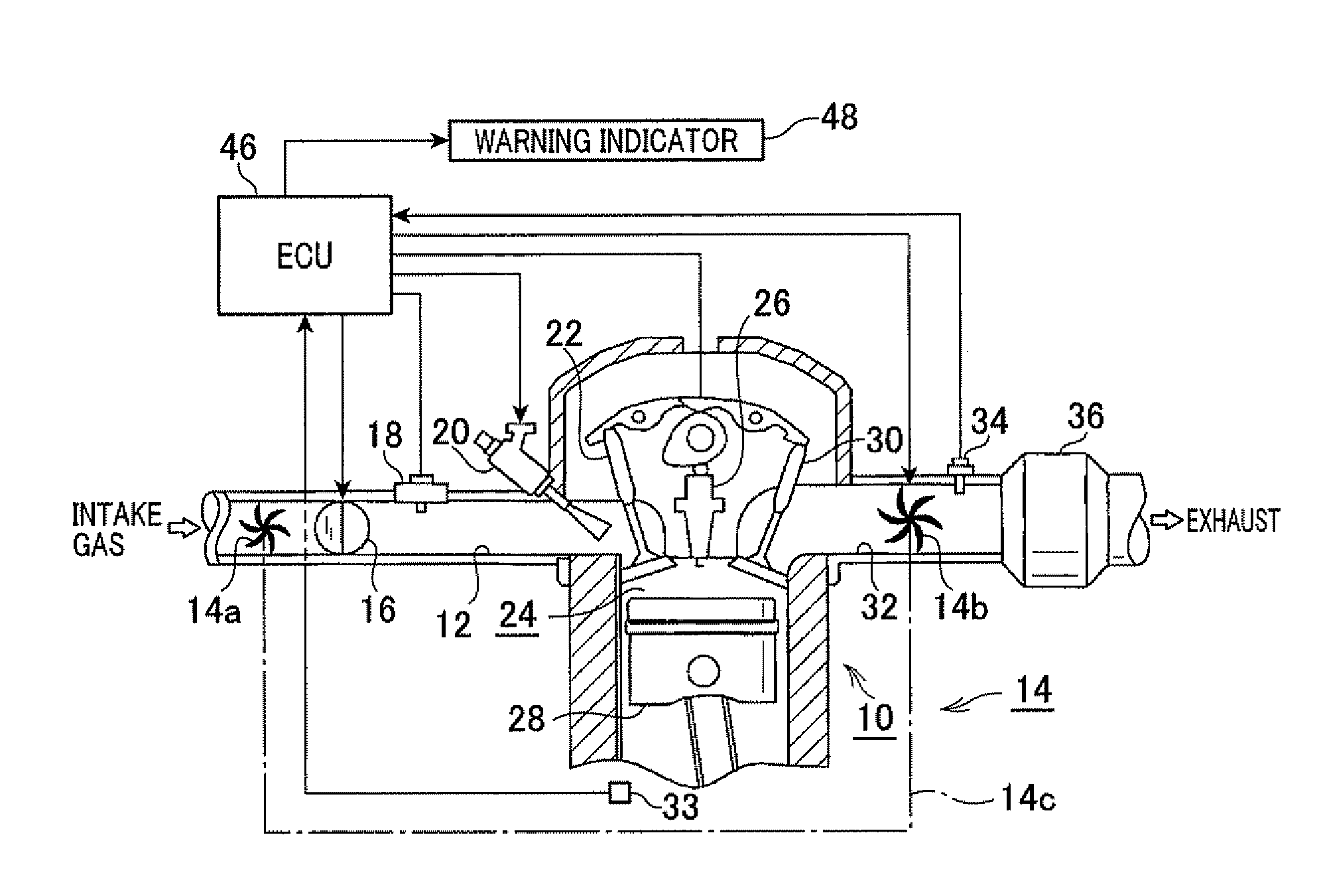
[0050]Referring to FIGS. 1 to 4 and FIGS. 5A to 5C first, hereinafter is described a first embodiment in which a control apparatus of the present invention is applied to a combustion control system of an on-vehicle internal combustion engine (gasoline engine).

[0051]FIG. 1 is a schematic diagram generally illustrating the combustion control system according to the first embodiment. As shown in FIG. 1, the combustion control system includes an engine 10 which is provided with an intake path 12. The intake path 12 includes, from its upstream side toward its downstream side, an intake compressor 14a provided in a turbocharger 14 described later, a throttle valve 16 and an intake pressure sensor 18 that detects a pressure (intake pressure) in the intake path 12. The throttle valve 16 is an electronically controlled member that regulates a quantity of air (air content or intake volume). Specifically, the opening of the throttle valve 16 (throttle position) is electronically controlled to ...

second embodiment

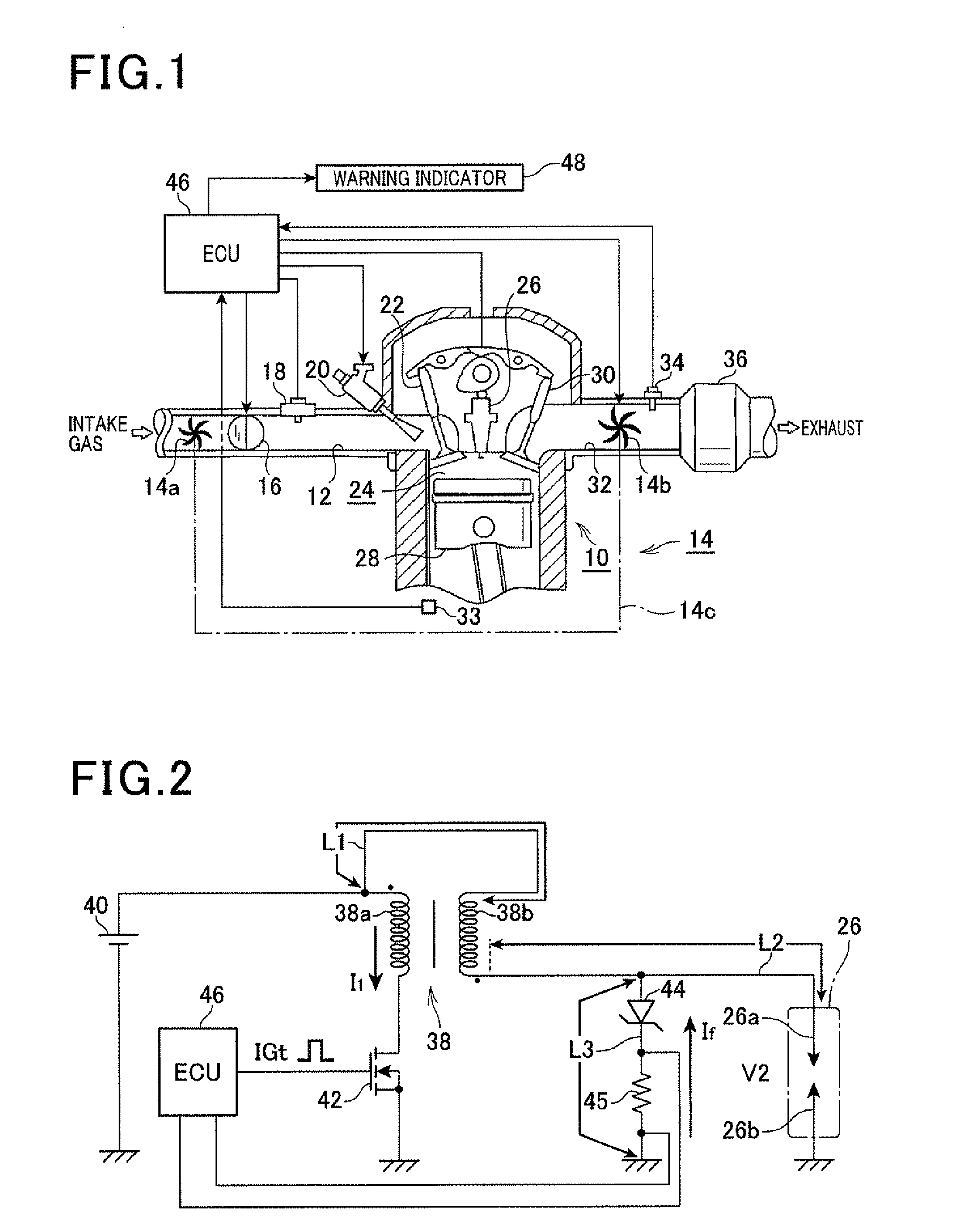
[0085]Referring now to FIG. 6, hereinafter is described a second embodiment of the present invention, focusing on the differences from the first embodiment. In the second and the subsequent embodiments as well as the modifications, the components identical with or similar to those in the first embodiment are given the same reference numerals for the sake of omitting unnecessary explanation.

[0086]FIG. 6 is a schematic diagram generally illustrating an ignition system according to the second embodiment. FIG. 6 omits the illustration of the ECU 46.

[0087]As shown in FIG. 6, in the second embodiment, one of two ends of the low-voltage side path L1, which is shown as a point “P” being connected to a secondary coil 38b, is connected to the connecting path L2 via a constant-voltage path L3a. The constant-voltage path L3a is provided with a resistor 45a and a Zener diode 44a therein which are positioned in this order from the point “P”. Specifically, a cathode of the Zener diode 44a is conne...

third embodiment

[0092]Referring to FIGS. 7 and 8, a third embodiment of the present invention is described focusing on the differences from the first embodiment.

[0093]In the third embodiment, the deterioration determination process is different from that of the first embodiment.

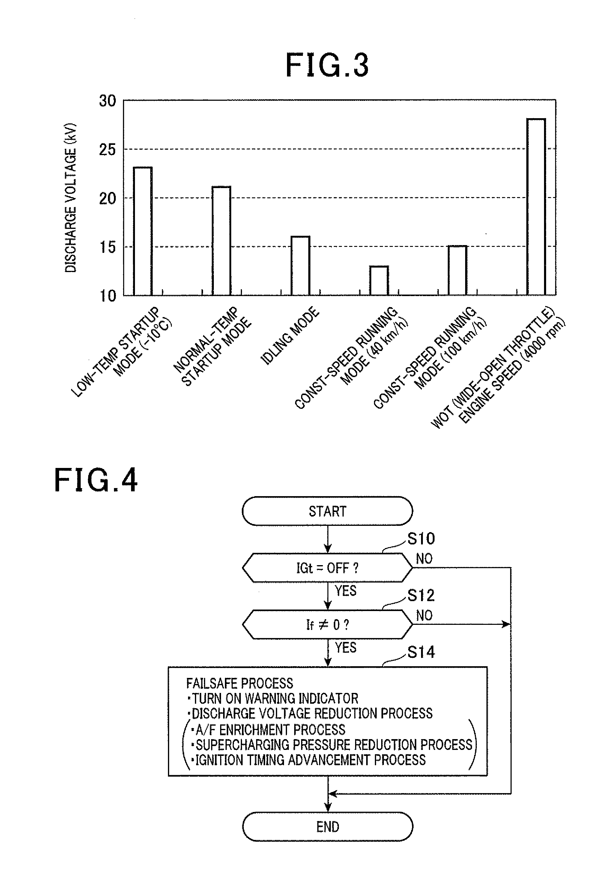
[0094]FIG. 7 is a flow diagram illustrating a series of steps of a deterioration determination process according to the third embodiment. This process is performed by the ECU 46.

[0095]At step S10, if an affirmative determination is made, control proceeds to step S12a. At step S12a, the ECU 46 determines whether or not the determination current If has a value other than zero in an If-detected period (period in which the determination current If is detected), i.e. whether or not current flows through the constant-voltage path L3. Specifically, as shown in FIGS. 8A to 8C, the ECU 46 determines whether or not the determination current If has a value other than zero in a period from time t1 when the on-ignition signal (IGt) is sw...


PUM


Abstract

A control apparatus for an ignition system of an internal combustion engine which can appropriately judge deterioration of a spark plug is disclosed. The ignition system includes a spark plug and a Zener diode. These are connected in parallel. In the ignition system, a constant-voltage path whose one of two ends is grounded is connected to the connecting path which connects the center electrode of the spark plug to a secondary coil. The constant-voltage path includes a Zener diode and a resistor. In a case where electric current is detected at the resister in a term from the start of current supply to a primary coil to the end, the control apparatus judges the spark plug being deteriorated.

Description

CROSS-REFERENCE TO RELATED APPLICATION[0001]This application is based on and claims the benefit of priorities from earlier Japanese Patent Application Nos. 2012-025108, 2012-025110 and 2012-195099 filed Feb. 8, 2012, Feb. 8, 2012 and Sep. 5, 2012, respectively, the descriptions of which are incorporated herein by reference.BACKGROUND OF THE INVENTION[0002]1. Technical Field of the Invention[0003]The present invention relates to a control apparatus for an internal combustion engine, which performs ignition control under which high voltage is applied across the electrodes of a spark plug based on electro-magnetic energy stored in a spark coil to produce discharge sparks across the electrodes and, in particular, to a control apparatus for an internal combustion engine, which is able to appropriately determine deterioration as being caused in the spark plug or determine the occurrence of an open failure in an ignition system. Herein, “open failure” means a defective state such that elec...

Claims


Application Information

Patent Timeline
IPC IPC(8): F02P17/12
CPCF02P17/12F02P11/06F02P3/0414
Inventor SHIBATA, MASAMICHIMIZUTANI, ATSUYAIMANAKA, YASUOMIHATTORI, KOICHI
Owner DENSO CORP
Why Eureka
Try Eureka