
Wind turbine and vibration damping method thereof

a technology of wind turbine and vibration damping, which is applied in the direction of rotors, vessel construction, marine propulsion, etc., can solve the problems of increasing the fatigue load of a structural material reducing the life of the wind turbine, and the vibration induced by the fluctuation of the wind speed flowing into the wind turbine cannot be ignored, so as to achieve a large damping effect

Inactive Publication Date: 2013-08-01
MITSUBISHI HEAVY IND LTD
View PDF2 Cites 49 Cited by
  • Summary
  • Abstract
  • Description
  • Claims
  • Application Information

AI Technical Summary

Benefits of technology

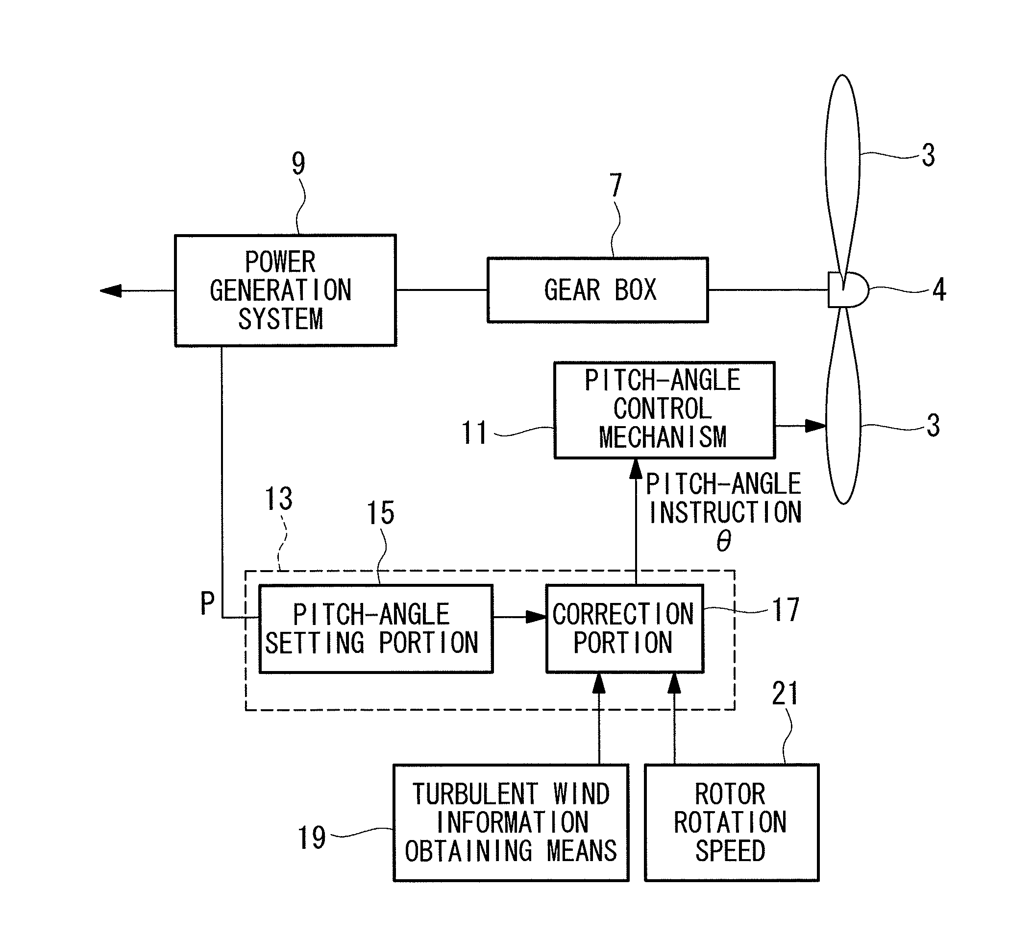
The present invention is a wind turbine that can effectively damp vibrations over a wide frequency range. An active damper is used to damp the wind turbine blades at a specific frequency, while a passive damper is made to bear the same frequency. This allows for efficient use of wind energy and damping of vibrations without adding extra weight to the wind turbine. The use of a tuned liquid damper or a tuned mass damper, both of which are existing wind turbine components, further reduces the need for additional components.

Problems solved by technology

Since a wind turbine has a structure in which heavy articles such as a wind-turbine blade, a gear box, a power generator and the like are mounted on an upper part of a tower having the height of several tens meters in general, vibration induced by fluctuation in the wind speed flowing into the wind turbine cannot be ignored.
Such vibration increases a fatigue load of a structural material of the wind turbine and reduces the life of the wind turbine.
However, the AMD requires an actuator which drives an added mass in addition to the added mass, whereby cost and weight are increased.
However, since an actuator which drives the added mass is still needed, the increase in weight is not fundamentally solved.
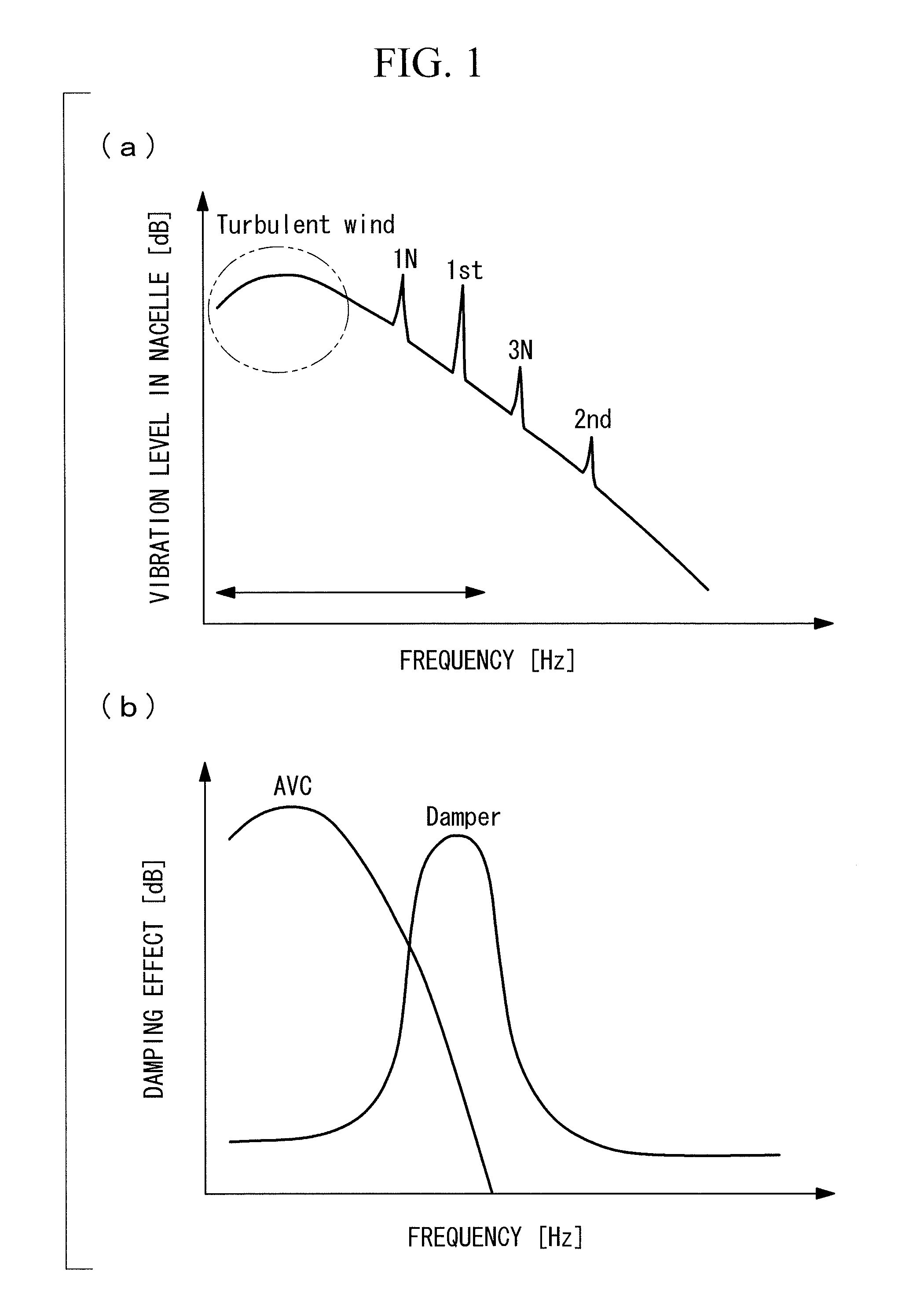
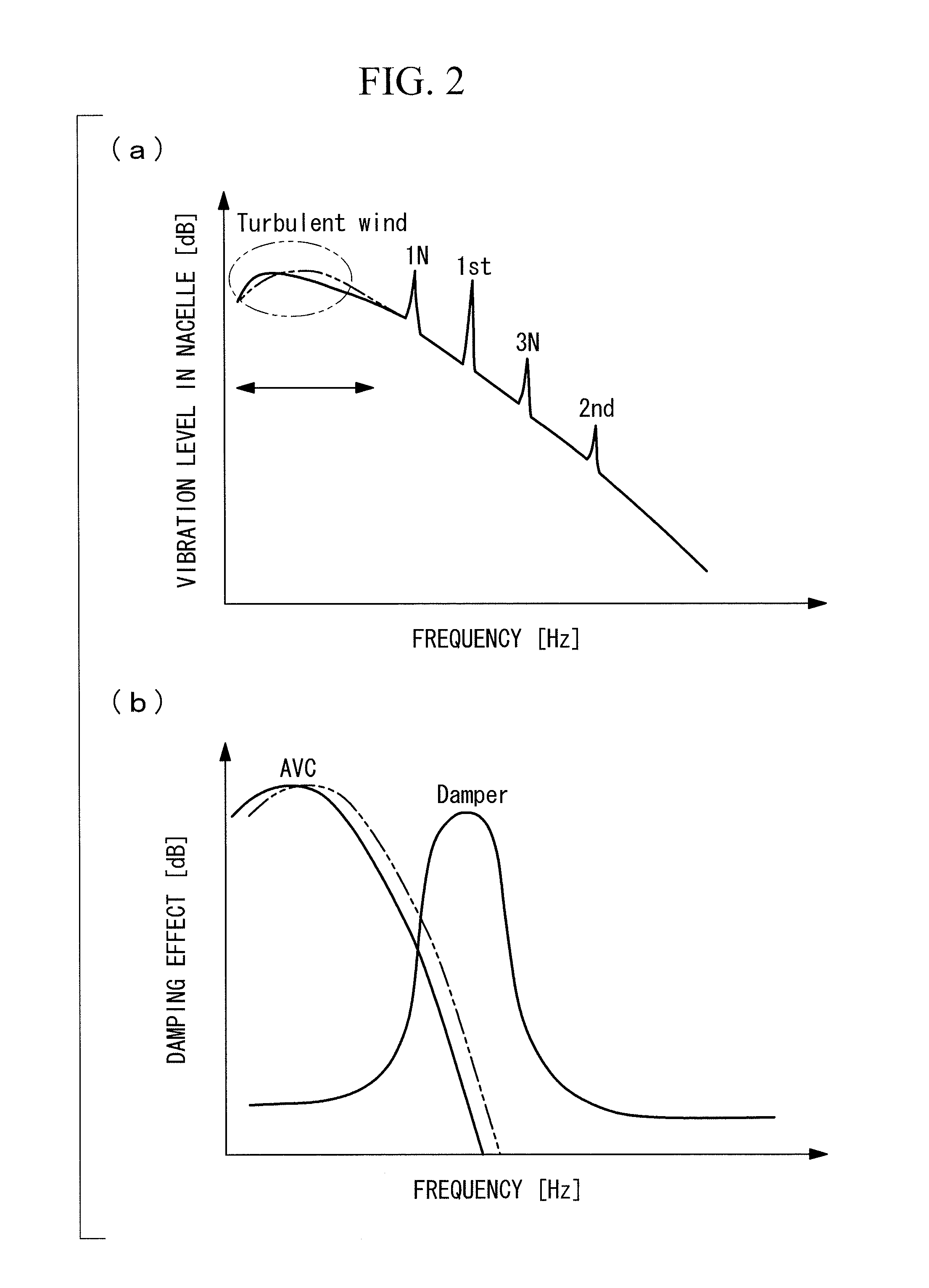
However, as illustrated in the figures, since a frequency band which needs to be damped is wide in a wind turbine, the following problems occur.
Therefore, it is difficult to obtain a large damping effect in all the frequency bands of vibration specific to a wind turbine.

Method used


Image

  • Wind turbine and vibration damping method thereof
  • Wind turbine and vibration damping method thereof
  • Wind turbine and vibration damping method thereof

Examples


Embodiment Construction

[0043]An embodiment according to the present invention will be described below by referring to the attached drawings.

[0044]FIG. 1 illustrates a basic idea of vibration damping of the present invention. The lateral axis of FIG. 1(a) indicates a frequency [Hz], and the vertical axis indicates a vibration level [dB] in a nacelle installed on an upper part of a tower of a wind turbine. As illustrated in FIG. 1(a), vibration caused by a frequency component of turbulent wind, vibration in a rotor rotation speed (1N), vibration in a primary component (1st) of a natural vibration frequency of the wind turbine itself, vibration in a rotation speed (3N) three times of the rotor rotation speed, and vibration in a secondary component (2nd) of the natural vibration frequency of the wind turbine itself appear in the order from the low-frequency side. The relationship between the frequency in the rotor rotation speed (1N) and the primary natural vibration frequency (1st) might be opposite dependin...


PUM


Abstract

There are provided a TMD adjusted to damp vibration in a natural frequency of a wind turbine, an AVC adjusted to damp vibration in a variable frequency of turbulent wind flowing into the wind turbine and / or a frequency of a rotation speed of a wind-turbine blade, and a pitch-angle control portion provided with a correction portion which adjusts a damping frequency of the AVC. The AVC is configured to obtain the damping force by changing the pitch angle of the wind-turbine blade.

Description

BACKGROUND OF THE INVENTION[0001]1. Field of the Invention[0002]The present invention relates to a wind turbine and a vibration damping method thereof.[0003]2. Description of Related Art[0004]A wind turbine which converts wind energy to electric power and generates the electric power has drawn attention as clean energy. Since a wind turbine has a structure in which heavy articles such as a wind-turbine blade, a gear box, a power generator and the like are mounted on an upper part of a tower having the height of several tens meters in general, vibration induced by fluctuation in the wind speed flowing into the wind turbine cannot be ignored. Such vibration increases a fatigue load of a structural material of the wind turbine and reduces the life of the wind turbine.[0005]On the other hand, high-rise structures such as a building employs AMD (Active Mass Damper) in order to damp vibration caused by wind. However, the AMD requires an actuator which drives an added mass in addition to t...

Claims


Application Information

Patent Timeline
Patent Type & Authority Applications(United States)
IPC IPC(8): F01D7/00
CPCF03D11/00Y02E10/722F05B2260/964F03D80/00Y02E10/72F16F7/1028F16F7/1034F16F7/104F03D7/0296
Inventor HAYASHI, KENTARONAGAI, NAOYUKIWAKASA, TSUYOSHI
Owner MITSUBISHI HEAVY IND LTD
Learn More