
Methods for separating glass substrate sheets by laser-formed grooves

a technology of laser-formed grooves and glass substrate sheets, which is applied in the direction of glass making apparatus, manufacturing tools, welding/soldering/cutting articles, etc., can solve the problems of increased geometric complexity of glass articles, weakened glass articles are susceptible to edge damage, and newly formed edges have not been formed

Active Publication Date: 2013-08-01
CORNING INC
View PDF36 Cites 105 Cited by
  • Summary
  • Abstract
  • Description
  • Claims
  • Application Information

AI Technical Summary

Benefits of technology

The patent describes a method of separating a glass article from a glass substrate sheet. The method involves focusing a laser beam on the substrate sheet and translating it along a groove line to form the groove. The groove has bevelled or chamfered walls and extends partially through the thickness of the substrate sheet. After forming the groove, the substrate sheet is strengthened. The glass article can then be separated from the substrate sheet along the groove, with the edges of the glass article being under compressive stress. The technical effect of the patent is to provide a reliable and efficient method for separating glass articles from glass substrate sheets.

Problems solved by technology

As the use of glass articles in various devices continues to expand, the geometric complexity of the glass articles also increases.
However, strengthened glass articles are susceptible to edge damage, especially after the glass articles are separated from a glass substrate sheet after the strengthening process has been performed.
In this case, the newly formed edges have not been ion-exchanged and are susceptible to damage from mechanical contact.
More specifically, separating the glass substrate after ion-exchange processing leaves the central tension layer exposed at the edges of the glass article, thereby leaving the edge susceptible to damage which may lead to catastrophic failure.

Method used


Image

  • Methods for separating glass substrate sheets by laser-formed grooves
  • Methods for separating glass substrate sheets by laser-formed grooves
  • Methods for separating glass substrate sheets by laser-formed grooves

Examples


Embodiment Construction

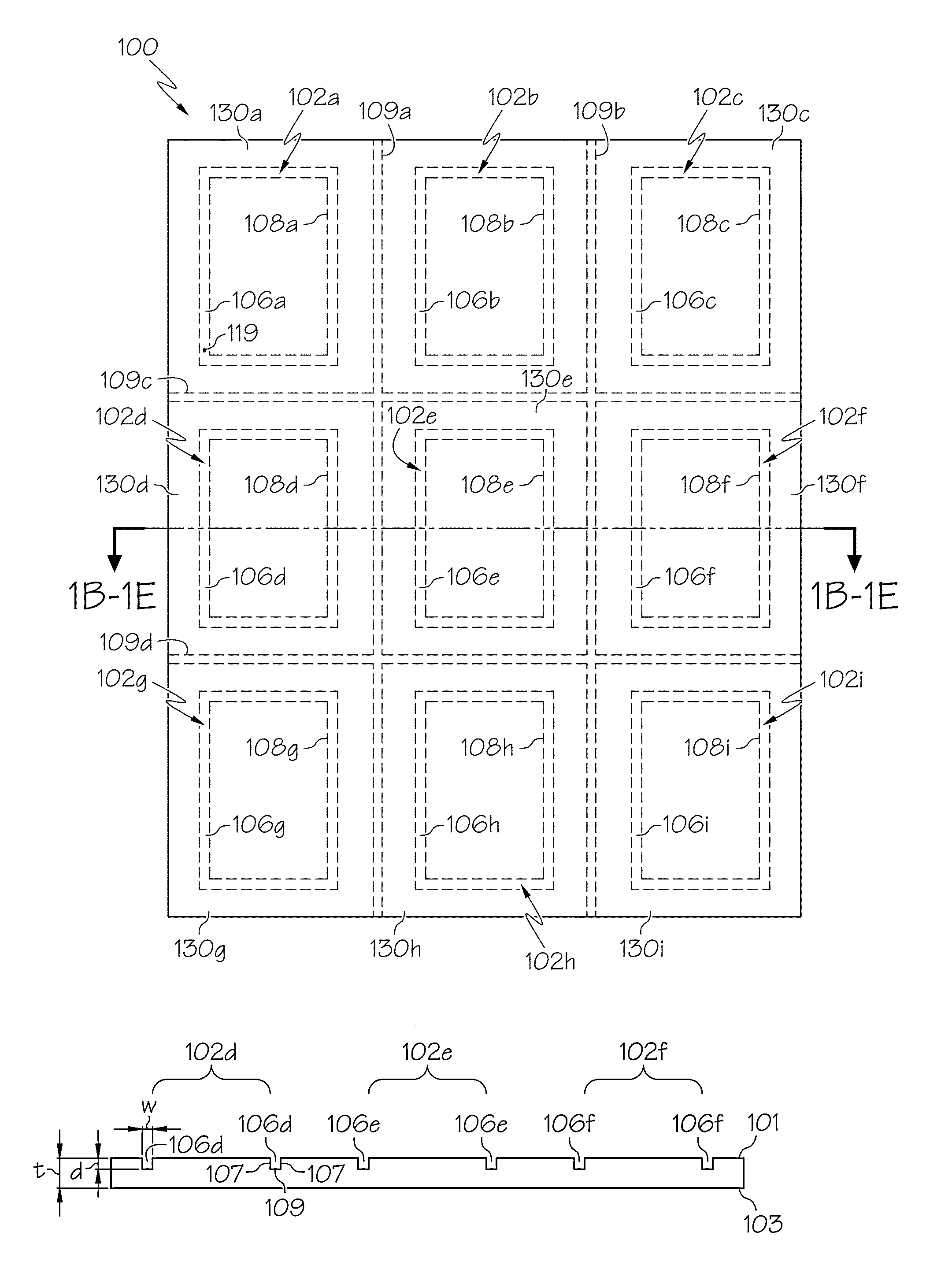
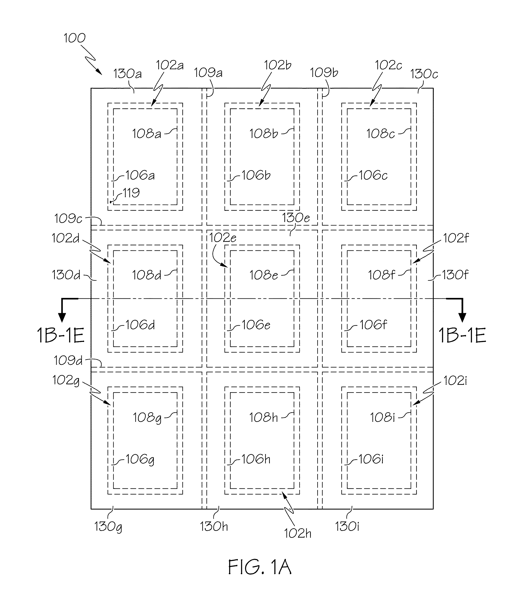
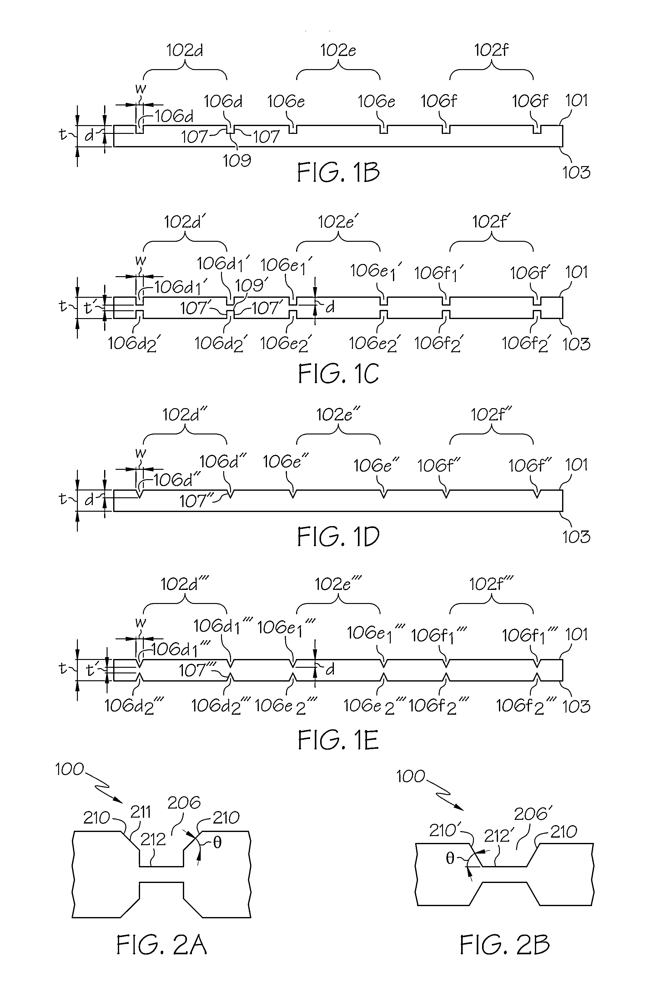
[0039]Reference will now be made in detail to various embodiments of methods for grooving and separating strengthened glass substrate sheets. FIGS. 1A-7D schematically depict various embodiments of methods for separating one or more strengthened glass articles from a strengthened glass substrate sheet by the formation of grooves. In one embodiment, the method generally comprises forming a groove within a non-strengthened glass substrate sheet. The groove is continuous and defines a perimeter of the glass article that will be separated from the glass substrate sheet. The groove extends partially through the thickness of the glass substrate sheet. After the groove (or grooves) is formed, the glass substrate sheet is strengthened by a strengthening process, such as an ion-exchange strengthening process. The strengthening process creates a compressive stress region on both surfaces, as well as the edges, of the glass article. The glass article is then separated from the now strengthened...


PUM

PropertyMeasurementUnit
thicknessaaaaaaaaaa
thicknessaaaaaaaaaa
thicknessesaaaaaaaaaa

Abstract

Methods for separating glass articles from glass substrate sheets are described herein. In one embodiment, a method includes focusing a laser beam on at least one surface of the glass substrate sheet such that the laser beam has an asymmetrical intensity distribution at the at least one surface of the glass substrate sheet. The method further includes translating the laser beam on the at least one surface of the glass substrate sheet along a desired groove line to form at least one groove on the at least one surface of the glass substrate sheet. The at least one groove extends partially through a thickness of the glass substrate sheet along the desired groove line and has bevelled or chamfered walls. The glass article may be separated from the glass substrate sheet along the at least one groove.

Description

[0001]This application claims the benefit of priority under 35 U.S.C. §119 of U.S. Provisional Application Ser. No. 61 / 521942 filed on Aug. 10, 2011 the content of which is relied upon and incorporated herein by reference in its entirety.BACKGROUND[0002]1. Field[0003]The present specification generally relates to separating glass substrate sheets and, more particularly, to forming grooves within a strengthened glass substrate sheet prior to a strengthening process to separate glass articles from strengthened glass substrate sheets.[0004]2. Technical Background[0005]Thin glass articles have a variety of applications in consumer electronic devices. For example, such glass articles may be used as cover sheets and / or touch screens for LCD and LED displays incorporated in mobile telephones, GPS devices, display devices such as televisions and computer monitors and various other electronic devices. As the use of glass articles in various devices continues to expand, the geometric complexi...

Claims


Application Information

Patent Timeline
Patent Type & Authority Applications(United States)
IPC IPC(8): C03B33/02
CPCC03B33/0222B23K2201/36C03B33/033C03C15/00C03C21/00C03C23/0025C03B23/02B23K26/0626B23K26/0635B23K26/0648B23K26/0665B23K26/367B23K26/38B23K26/421B23K2201/34B23K26/4075B23K26/364B23K26/0624B23K26/60B23K26/40C03C15/02C03C21/002B23K2101/35B23K2101/36B23K2103/50
Inventor BLACK, MATTHEW L.CORNEJO, IVAN A.DRAKE, MELINDA ANNGOMEZ, SINUEMOORE, LISA ANNTSUDA, SERGIO
Owner CORNING INC
Learn More