Personal Electronic Target Vision System, Device and Method

Active Publication Date: 2013-07-25
ACCIPITER RADAR TECH
View PDF7 Cites 28 Cited by
  • Summary
  • Abstract
  • Description
  • Claims
  • Application Information

AI Technical Summary

Benefits of technology

This patent describes a surveillance system that allows users to filter or select which targets they are interested in seeing on a display. Users can also set speed and headings constraints to narrow down their field of view and display only the targets that meet their specific needs. This feature is particularly useful in dense target environments to reduce workload and increase efficiency. Additionally, users can set particular targets to be displayed whenever they are present in their field of view. Overall, this system improves situational awareness and efficiency for users by allowing them to define their own visual reference points and quickly identify relevant targets.

Problems solved by technology

For example, airports span thousands of acres in extent and birds approaching active runways and critical aircraft flight corridors pose a significant hazard to aviation safety.
While these help improve a user's natural vision with the ability to zoom to distant targets and allowing targets to be seen at night, they are labor intensive and difficult to use when multiple targets are present over vast areas at different ranges, bearings and altitudes.
The sensor's maximum range is also limited; and at an airport, for instance, view will be blocked by urban structures such as airport terminal buildings.
As a result, targets such as birds will only be seen in the vicinity of the user, unless multiple persons are deployed around the airport at all times, which is expensive.
Finally, target information can not be easily shared with other remote users unless high-bandwidth network links are provided to move video, for example, from a head-mounted camera to a remote user; and multiple remote users can not independently control the user-carried sensor for their own viewing purposes.
A platform-mounted sensor such as radar mounted on an agile police vessel carrying a few police officers is also limited in performance.
Line of sight coverage is limited (because of the low height above the water available for mounting the sensor) to within a few kilometers of the vessel.
If the police vessel responds at night by chasing a target of interest, radar performance will severely degrade due to the impact of vessel dynamics on sensor performance, resulting in target loss.
A large number of vessels with radars are needed to monitor vast water areas, making such a system extremely expensive.
And the display of targets by the vessel radar is not user-centric; rather it is vessel-centric (e.g. heads-up display) or north-centric (north-up display) making it more difficult for individual users to understand their situation, and stay locked on assigned targets, especially in crowded target environments.
While this earth-centric view is valuable to centralized operators, it is lacking for individual responders who are on the move and attempting to respond to particular targets of interest.
The position and orientation of the responder is often not captured by the COP; and transforming from an earth-centric display to a user-centric display coupled with directing one's eyes to visually acquire a target of interest is difficult and non-intuitive.
As a result, finding targets of interest with the aid of the COP is very challenging.

Method used


Image

  • Personal Electronic Target Vision System, Device and Method
  • Personal Electronic Target Vision System, Device and Method
  • Personal Electronic Target Vision System, Device and Method

Examples


Embodiment Construction

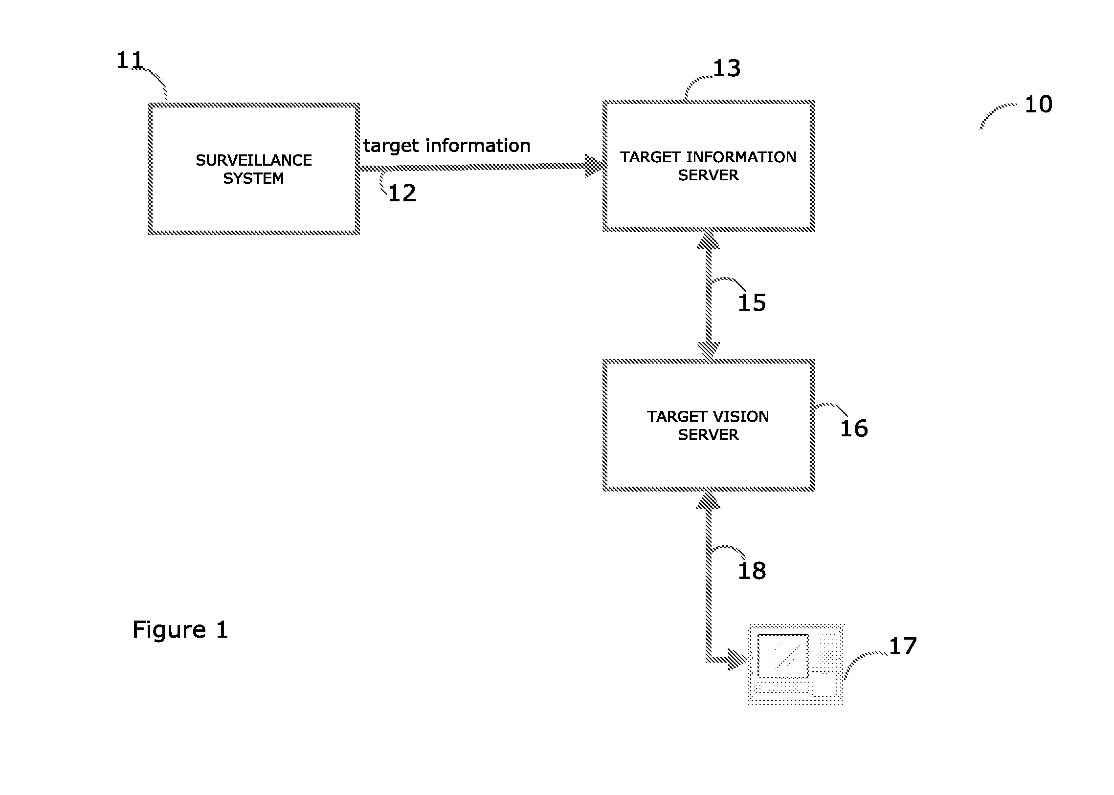
[0054]A personal electronic target vision system in accordance with the present invention displays targets of interest (TOIs) to one or more users relative to each user's respective location. With a personal electronic vision device (PEVD) carried by a user, targets in the field of view (FOV) of each user are rendered in real-time to the user so that each user can visualize where the targets are relative to himself, with an aspect analogous to how the targets would be seen with the human eye, either directly or via an optical instrument.

[0055]The applications for a user-centric, personal target vision system in accordance with the present invention are numerous. In several respects, a super-human, synthetic target vision capability results which assists users in finding TOIs quickly and intuitively, better than they could be found with the unaided or optically aided eye. In homeland security applications, responders gain local awareness and safety by being able to find and focus on ...


PUM


Abstract

A personal, electronic target vision system renders targets in the field of view of the user in real-time so that the user can visualize where the targets are relative to him, in an orientation analogous to unaided human vision. An electronic vision device exchanges target selection information with a target vision server which returns to the electronic vision device the corresponding selected target location information for rendering selected targets in accordance with the user's changing viewpoint. The target vision server queries a target information server in order to access, filter and provide the real-time target location information required by the electronic vision device. A surveillance system of sensors and target tracking systems provides the target information server with target location information.

Description

FIELD OF THE INVENTION[0001]This invention relates to devices and methods that allow an individual to visualize, through electronic means, targets of interest and their locations; and the invention also relates to cloud computing and cloud services. The invention is particularly useful for visually rendering targets in a person's field of view that are too far away to see or too difficult to find by visual observation, unaided or with an optical instrument.BACKGROUND OF THE INVENTION[0002]Several applications require the means for individuals to easily locate targets of interest over large geographic regions. For example, airports span thousands of acres in extent and birds approaching active runways and critical aircraft flight corridors pose a significant hazard to aviation safety. If a trained wildlife biologist can locate such birds in a timely manner and respond to them, pyrotechnics or other techniques can be used to persuade the birds to alter their course, reducing the risk ...

Claims


Application Information

Patent Timeline
IPC IPC(8): G09G5/00
CPCG01S7/04G01S13/00G02B27/017G02B27/0189G02B2027/014G01S13/88G06T7/20H04N7/18G02B27/0172G01S13/42
Inventor NOHARA, TIMOTHY J.
Owner ACCIPITER RADAR TECH
Why Eureka
Try Eureka