
Power Assisted Vehicles

a technology of assisted vehicles and power, applied in the direction of battery/cell propulsion, position/direction control, human/animal propulsion, etc., can solve the problems of difficulty in ensuring the safety of the rider, wasting power unnecessarily on level terrain, and requiring a heavier, heavier and more expensive battery than is actually required

Inactive Publication Date: 2013-07-11
GALE STEPHEN WILLIAM
View PDF12 Cites 60 Cited by
  • Summary
  • Abstract
  • Description
  • Claims
  • Application Information

AI Technical Summary

Benefits of technology

The patent is about a pedaling sensor that can be adjusted to different positions to affect its performance. It can be an induction sensor mounted in a flexible housing or an induction coil with a ferritic core. The sensor can detect changes in the pedal assembly, making it easier to monitor the efficiency of the ride.

Problems solved by technology

This tends to mean that they waste power unnecessarily on level terrain.
As a result the bicycle is required to carry a larger, heavier and more expensive battery than is actually required.
On ascending a hill the rider can use the throttle to control the power applied by the motor to increase the assistance provided by the electric motor however it is often difficult for the rider to control that power efficiently.
This type of system however does not actually sense the effort needed to ascend the hill and requires a relatively delicate component to be placed in a vulnerable location on the bicycle rear wheel.
In addition this type of system is difficult to retrofit to existing bicycle frames as the sensor is required to he mounted “in series” with the hub sprocket of the rear wheels.

Method used


Image

  • Power Assisted Vehicles
  • Power Assisted Vehicles
  • Power Assisted Vehicles

Examples


Embodiment Construction

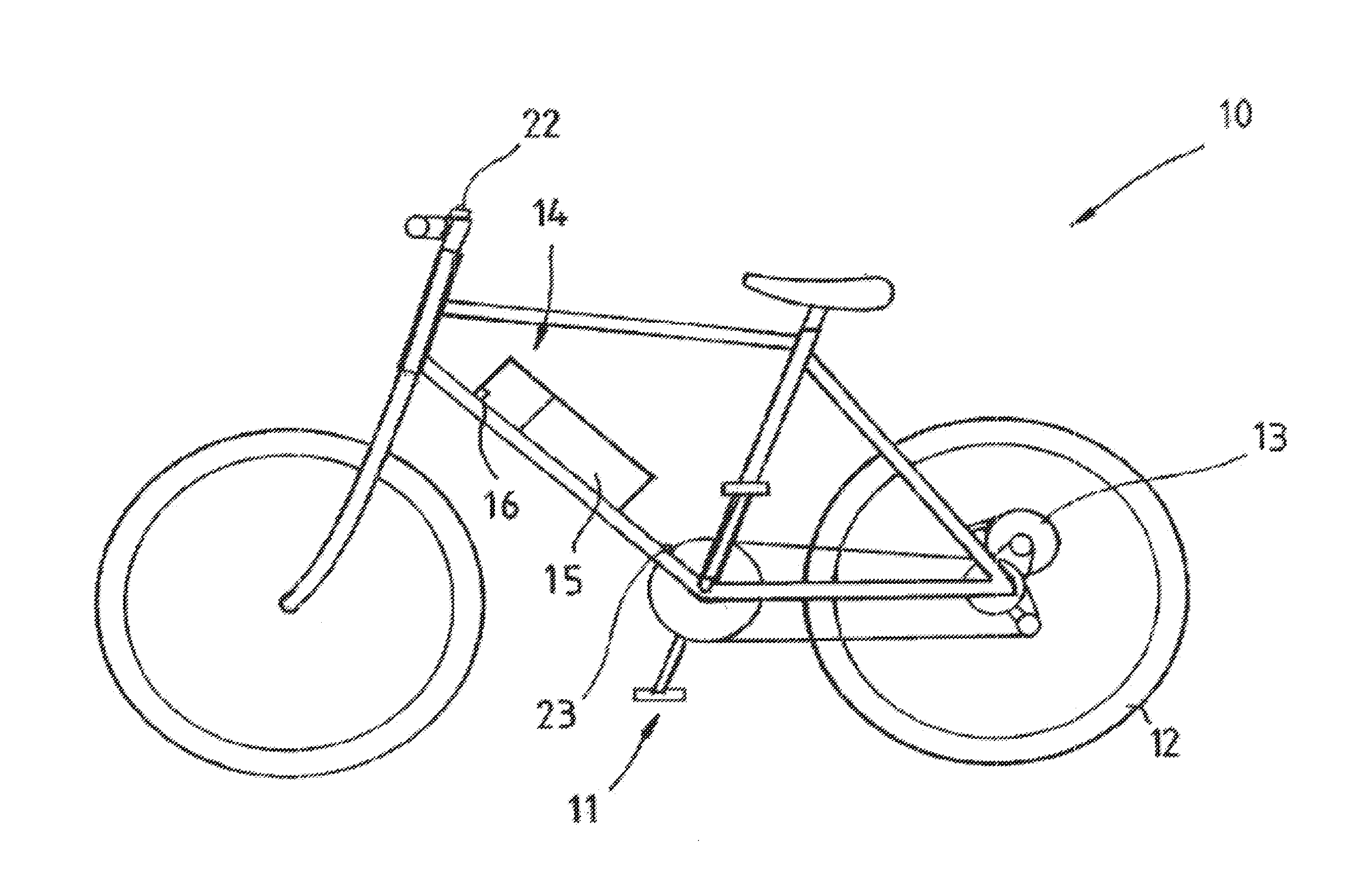
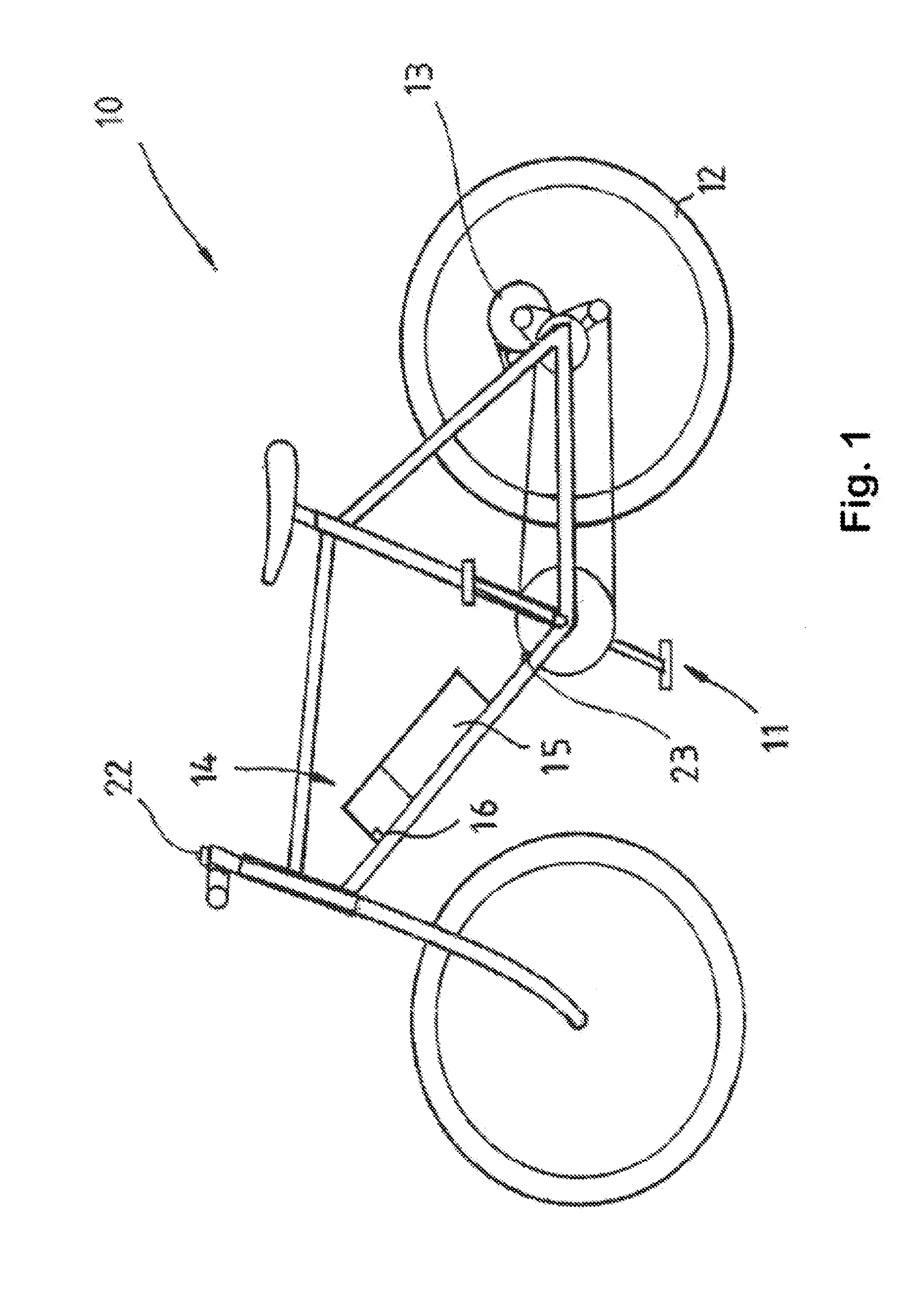
[0036]Referring to the drawings and firstly to FIG. 1 there is illustrated a typical, power assisted bicycle 10 provided with, a pedalling assembly 11 through which a manually provided pedalling power or force can be transmitted to the rear wheel 12 of the bicycle 10 to propel the bicycle 10. The bicycle 10 also includes an electric motor 13 for providing motive power assistance to the bicycle 10, the electric motor 13 typically being a brushless DC motor and being mounted by a suitable mounting or bracket on the rear forks of the bicycle 10, the motor 13 being coupled to the rear wheel 12 through any suitable transmission for example a belt or chain transmission for transmission of motive power to the rear wheel 12.

[0037]It will be appreciated that the bicycle 10 may be of many different designs other than that illustrated and may have either its rear wheel or front wheel equipped with the motor 13 for providing power assistance to the bicycle 1.0. The motor 13 may be mounted to th...


PUM


Abstract

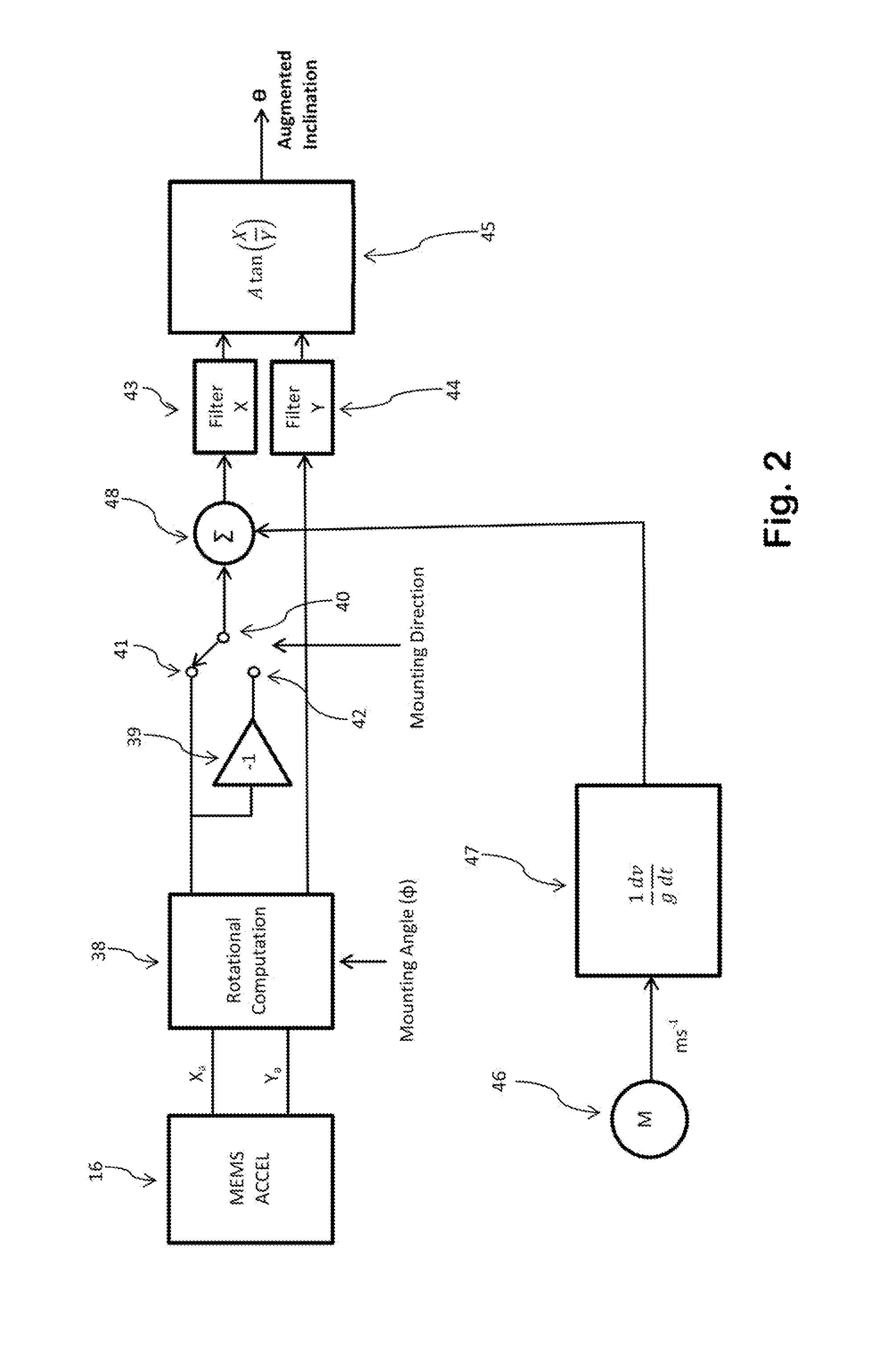
This invention relates to power assisted vehicles (10) and in particular to vehicles of the type which use electrically powered motors (13) to assist in the propulsion, of the vehicle. The control system (14) for a power assisted vehicle (10) having an electric motor (13), said control system (14) including: an accelerometer-based tilt sensor (16) augmented with an input from a velocity source (46) to determine the inclination of said vehicle (10), a manual input variably adjustable sensor (23) for detecting in a non-contact manner manual propulsion input, to said vehicle (10), by sensing the rotation speed of a rotating portion of said vehicle (10); and said control system (14) being adapted to control the power supplied to said motor (13) and therefore the power assistance provided to said vehicle (10) by said electric motor (13) in accordance with, the inclination or pitch of said vehicle (10) as sensed by said augmented accelerometer-based tilt sensor (16) and the manual propulsion input from said manual propulsion sensor (23).

Description

CROSS REFERENCE TO RELATED APPLICATIONS [0001]This application is a continuation-in-part application of U.S. patent application Ser. No, 12 / 828,499 filed on Jul. 1, 2010 now pending and incorporated by reference herein.TECHNICAL FIELD [0002]This invention relates to power assisted vehicles and in particular to vehicles of the type which use electrically powered motors to assist in the propulsion of the vehicle. More particularly, the present invention relates to electrically powered bicycles or other similar vehicles such as tricycles which are designed to he propelled by human power but which also include an electric motor to assist in the propulsion of the vehicle or to he a substitute for the normal rider-propulsion of the bicycle.BACKGROUND ART [0003]Motorized bicycles normally are designed to be pedalled by a rider and in addition include a small electric motor or internal combustion engine to assist in propelling the bicycle either when the rider is pedalling or not. Thus a bi...

Claims


Application Information

Patent Timeline
IPC IPC(8): B62M6/50B62K11/00
CPCB62K2207/04Y02T10/7275B60L11/007B60L11/1877B60L2240/12B60L2270/145Y02T10/7005B62M6/45B60L3/0023B60L11/1801B60L15/20B60W20/00B60L2200/12B60W2300/36B60W2520/16B60W2710/083B62M6/50B62K11/00Y02T10/648B62M6/60Y02T10/705B60L3/0061B60L50/20B60L50/53B60L50/66B62J45/4152Y02T10/64Y02T10/70Y02T10/72
Inventor GALE, STEPHEN WILLIAM
Owner GALE STEPHEN WILLIAM
Learn More