Fuel cell system
- Summary
- Abstract
- Description
- Claims
- Application Information
AI Technical Summary
Benefits of technology
Problems solved by technology
Method used
Image
Examples
Embodiment Construction
[0019]Descriptions of embodiments to carry out the present invention are now made below with reference to accompanied drawings.
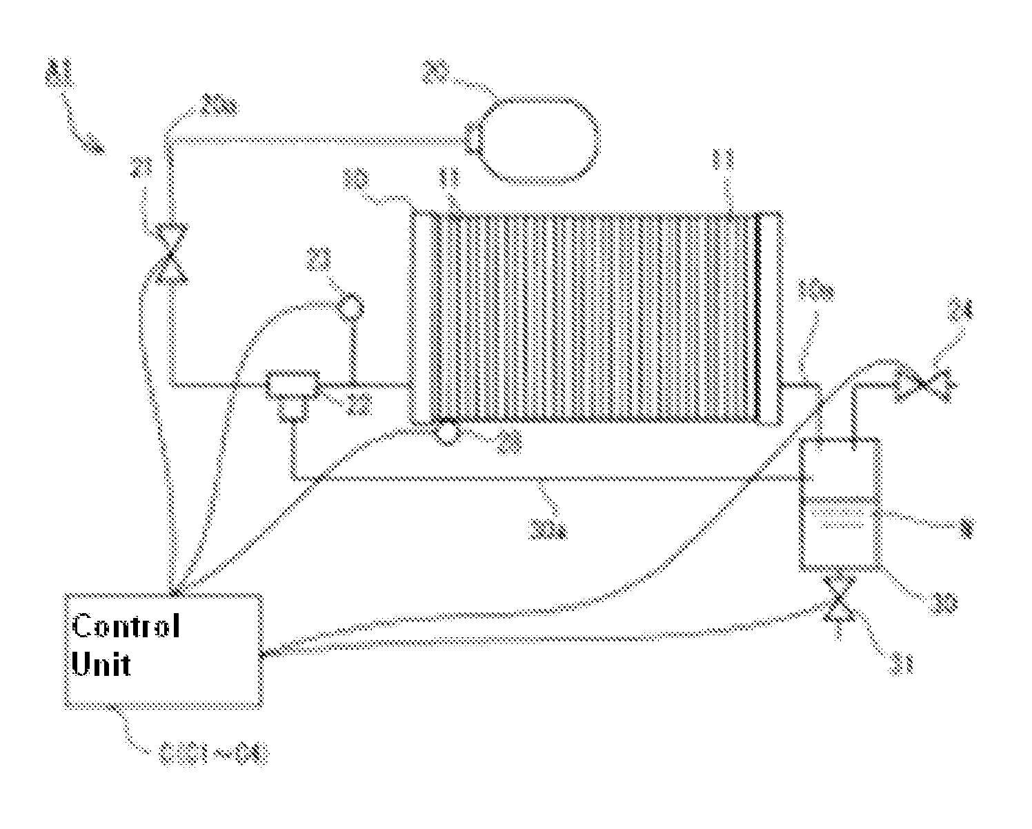
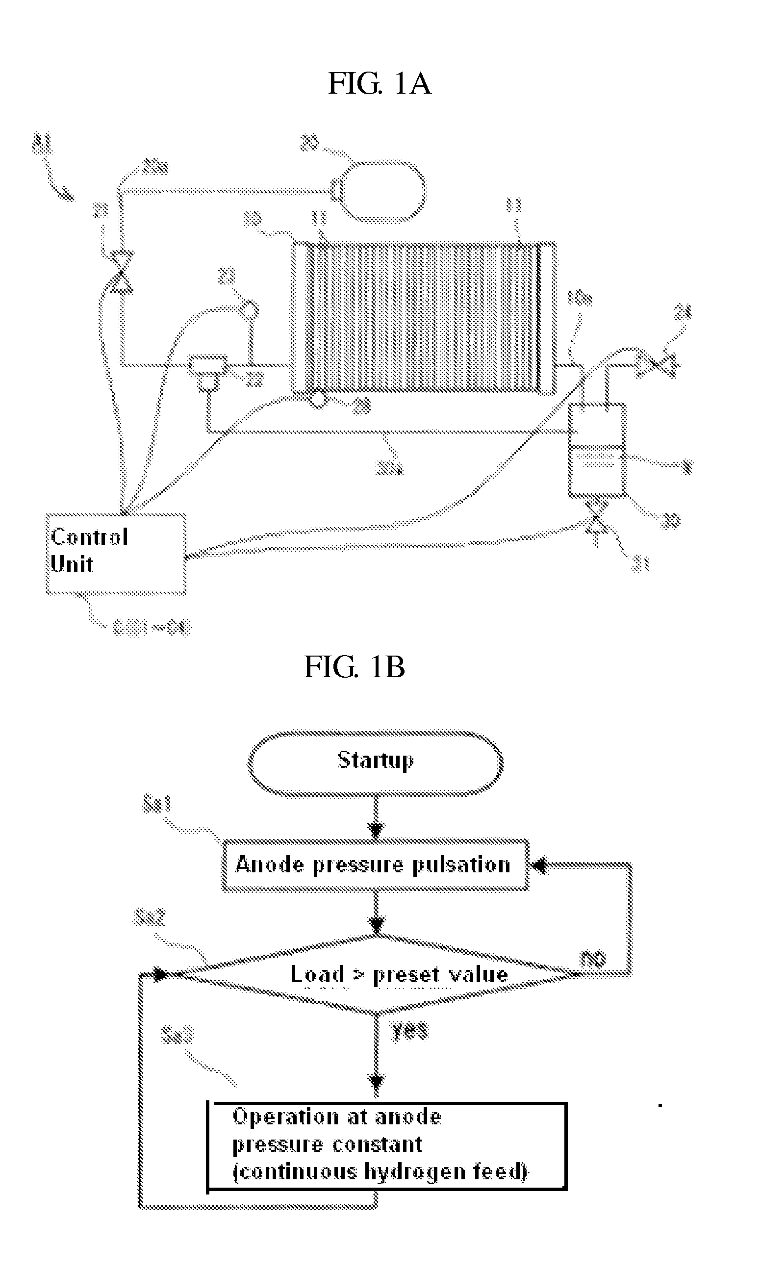
[0020]FIG. 1A is an explanatory diagram showing a schematic configuration of a fuel cell system A1 according to a first embodiment of the present invention, and FIG. 1B is a flowchart showing the operations of the fuel cell system A1 at the time of startup.
[0021]Note that, in FIGS. 1, 3, 5 and 6, among circulation systems of hydrogen-containing gas and oxygen-containing gas, only that for hydrogen-containing gas is illustrated and thus the diagram is somewhat simplified by omitting the illustration of the circulation system for oxygen-containing gas.
[0022]The fuel cell system A1 in the first embodiment according to the present invention is configured to include, in addition to cell stack 10, a fuel tank 20, a pressure regulating valve or modulator 21, an ejector 22, a pressure sensor 23, a temperature sensor 28, a nitrogen purge valve 24, a separate tank 30,...
PUM
 Abstract
Description
Claims
Application Information
 - R&D
- Intellectual Property
- Life Sciences
- Materials
- Tech Scout
- Unparalleled Data Quality
- Higher Quality Content
- 60% Fewer Hallucinations
Browse by: Latest US Patents, China's latest patents, Technical Efficacy Thesaurus, Application Domain, Technology Topic, Popular Technical Reports.
© 2025 PatSnap. All rights reserved.Legal|Privacy policy|Modern Slavery Act Transparency Statement|Sitemap|About US| Contact US: help@patsnap.com


