Image encoding apparatus, image encoding method and program
a technology of image encoding and image encoding, applied in the field of image encoding apparatus, image encoding methods and programs, can solve the problems of increasing costs and diadvatageously difficult nonlinearly identifying a characteristic of a block, and achieve the effect of improving subjective image quality
- Summary
- Abstract
- Description
- Claims
- Application Information
AI Technical Summary
Benefits of technology
Problems solved by technology
Method used
Image
Examples
first embodiment
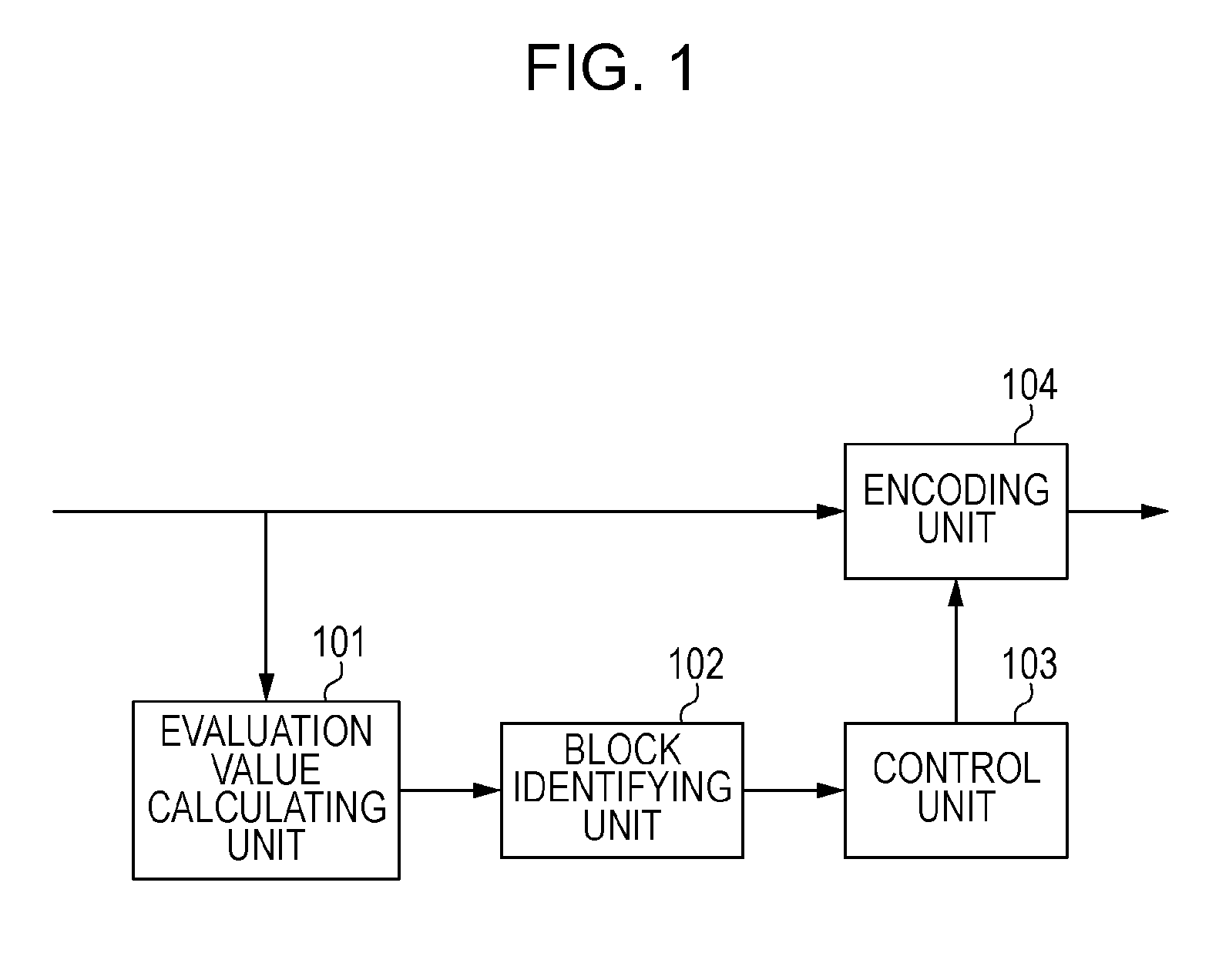
[0020]A first embodiment of the present invention will be described below with reference to drawings. FIG. 1 is a block diagram illustrating an image encoding apparatus according to this embodiment.
[0021]Referring to FIG. 1, an evaluation value calculating unit 101 calculates an evaluation value of an input image. The evaluation value calculating unit 101 receives input of an image of a block and calculates a plurality of evaluation values for the block. A block identifying unit 102 generates identification information on the basis of a plurality of evaluation values. A controller 103 determines a quantization parameter for the block on the basis on the identification information. An encoding unit 104 encodes the input image. The encoding unit 104 receives input of an image of a block, encodes the block on the basis of the quantization parameter generated by the controller and thus generates an encoded stream.
[0022]An operation of the image encoding apparatus of this embodiment will...
second embodiment
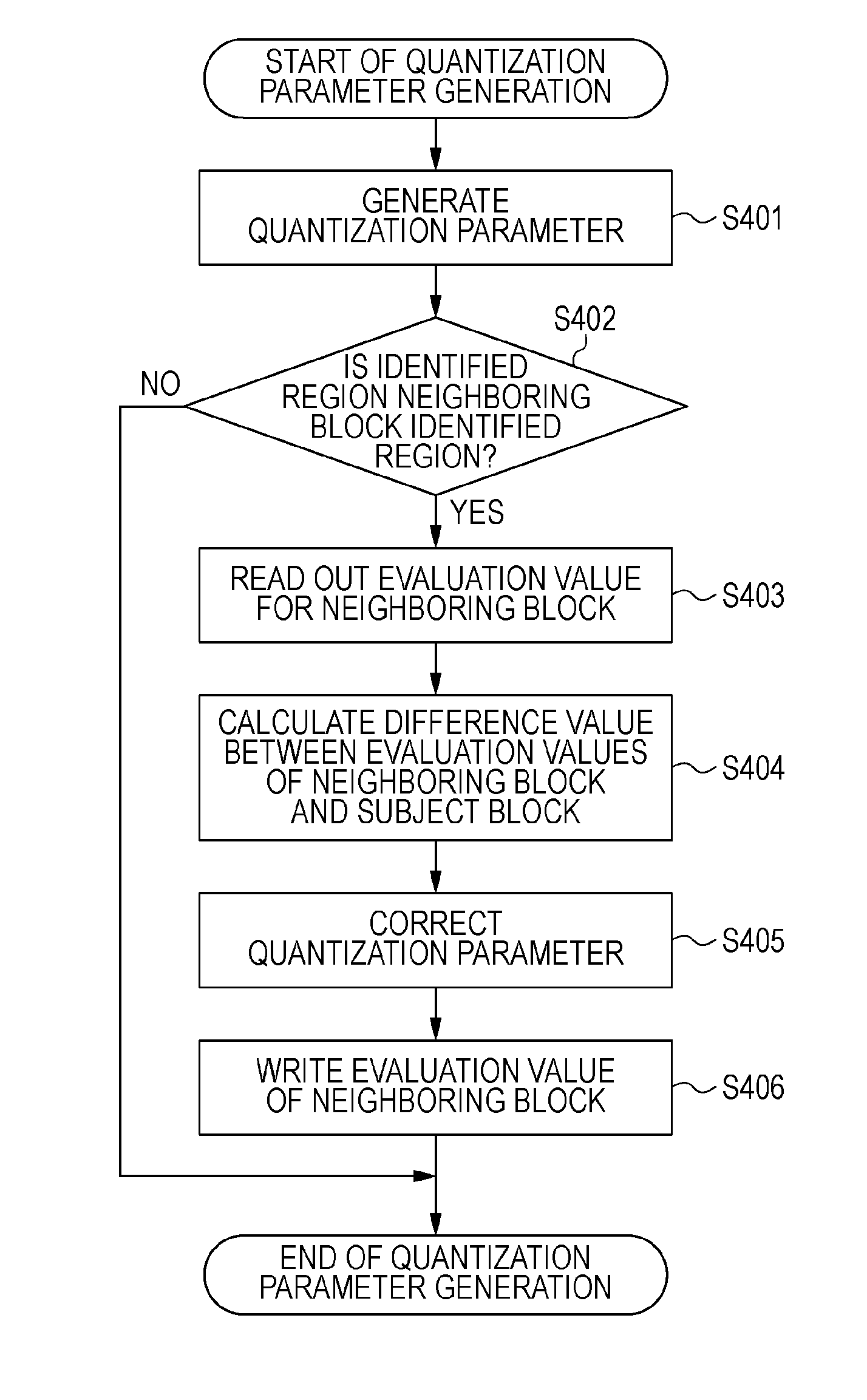
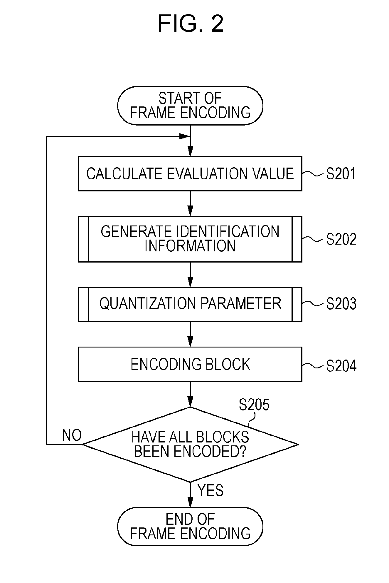
[0035]An image encoding apparatus of a second embodiment according to the present invention will be described. The configuration of an image encoding apparatus of this embodiment is the same as the configuration of the image encoding apparatus of the first embodiment illustrated in FIG. 1. The operation of the image encoding apparatus of this embodiment is also the same as that of the first embodiment illustrated in the flowchart in FIG. 2. The identification information generation method (step S202) illustrated in the flowchart in FIG. 3 is the same as that of the first embodiment. Therefore, the description will be omitted. According to this embodiment, the quantization parameter generation method (step S203) is different from that of the first embodiment in that not only block identification information but also the complexity of an adjacent block are used to determine the quantization parameter with high accuracy. With reference to FIG. 8, the effect of the use of the complexity...
third embodiment
[0042]An image encoding apparatus according to a third embodiment will be described. This embodiment uses three evaluation values of prediction information in addition to a luminance average value, a luminance complexity of a block. The term, “prediction information”, refers to data for prediction encoding such as motion vector information, and adjacent pixel value information in H.264 encoding method. FIG. 5 is a block diagram illustrating a configuration of an image encoding apparatus of this embodiment.
[0043]Referring to FIG. 5, a predicting unit 501 performs prediction processing for prediction encoding on the basis of an input image, and an evaluation value calculating unit 502 calculates an evaluation value of an input image. The evaluation value calculating unit 502 receives the input of an image of a block, calculates a plurality of evaluation values of the block and calculates prediction information associated with a result of the prediction processing from the predicting u...
PUM
 Abstract
Description
Claims
Application Information
 - R&D
- Intellectual Property
- Life Sciences
- Materials
- Tech Scout
- Unparalleled Data Quality
- Higher Quality Content
- 60% Fewer Hallucinations
Browse by: Latest US Patents, China's latest patents, Technical Efficacy Thesaurus, Application Domain, Technology Topic, Popular Technical Reports.
© 2025 PatSnap. All rights reserved.Legal|Privacy policy|Modern Slavery Act Transparency Statement|Sitemap|About US| Contact US: help@patsnap.com


