
Lamp

a technology of lamp and surface, applied in the field of lamps, to achieve the effect of effectively using the surface, less affected by heat, and less affected by the effect of ligh

Inactive Publication Date: 2013-07-04
PANASONIC CORP
View PDF0 Cites 41 Cited by
  • Summary
  • Abstract
  • Description
  • Claims
  • Application Information

AI Technical Summary

Benefits of technology

The patent describes a lamp that uses semiconductor light-emitting elements to produce light. The lamp has a circuit unit that is placed at the side of the primary reflective mirror, which is the main reflective surface in the lamp. This placement helps to minimize the impact of heat generated by the semiconductor elements on the circuit unit. This reduces the need for additional heat dissipation measures and allows the lamp to effectively use the light emitted. The lamp may also have a secondary reflective surface on the circuit case, which can further enhance the use of the light emitted. Additionally, the lamp may have a light focusing member, such as a reflector or lens, to help focus the light emitted from the semiconductor elements. The semiconductor elements and the light focusing member can be mounted on a mounting board for easy handling. The lamp may also have a front plate that eliminates the need for a separate attachment member for the circuit unit. Overall, the patent describes a lamp that is efficient in using the light emitted and minimizes the impact of heat on the circuit unit.

Problems solved by technology

The LEDs generate heat when emitting light; however, electronic components that constitute the circuit unit include a component having a low tolerance to heat load.

Method used


Image

  • Lamp
  • Lamp
  • Lamp

Examples


embodiment 1

[0045]The following describes in detail Embodiment 1 of the present invention, with reference to the drawings.

1. Overall Structure

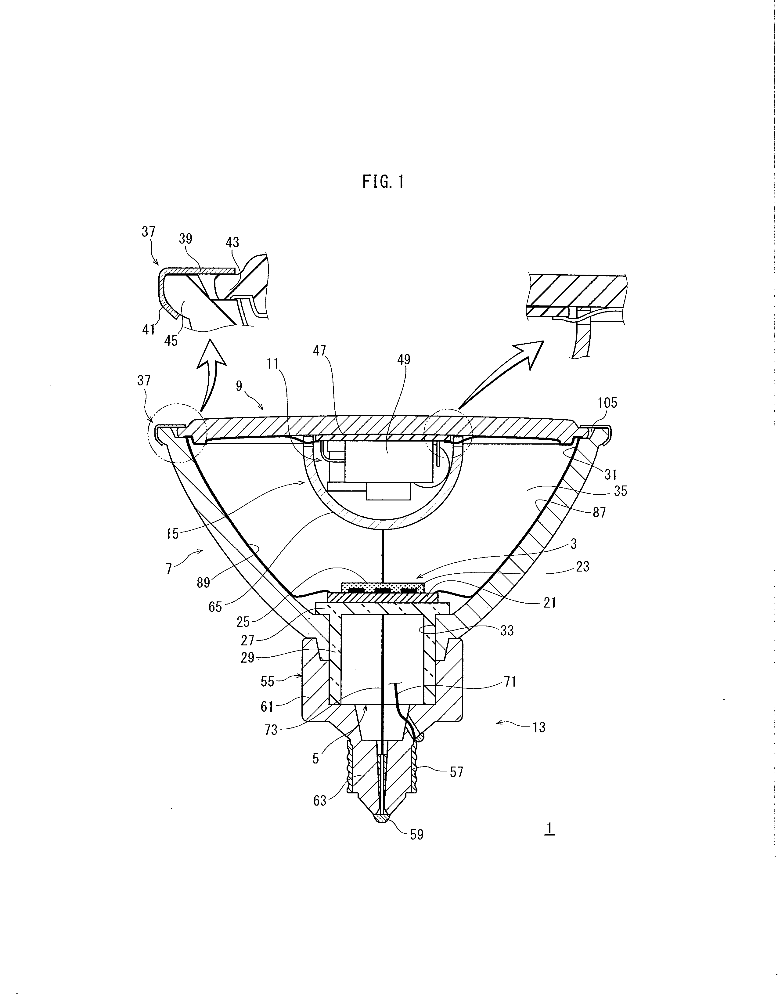
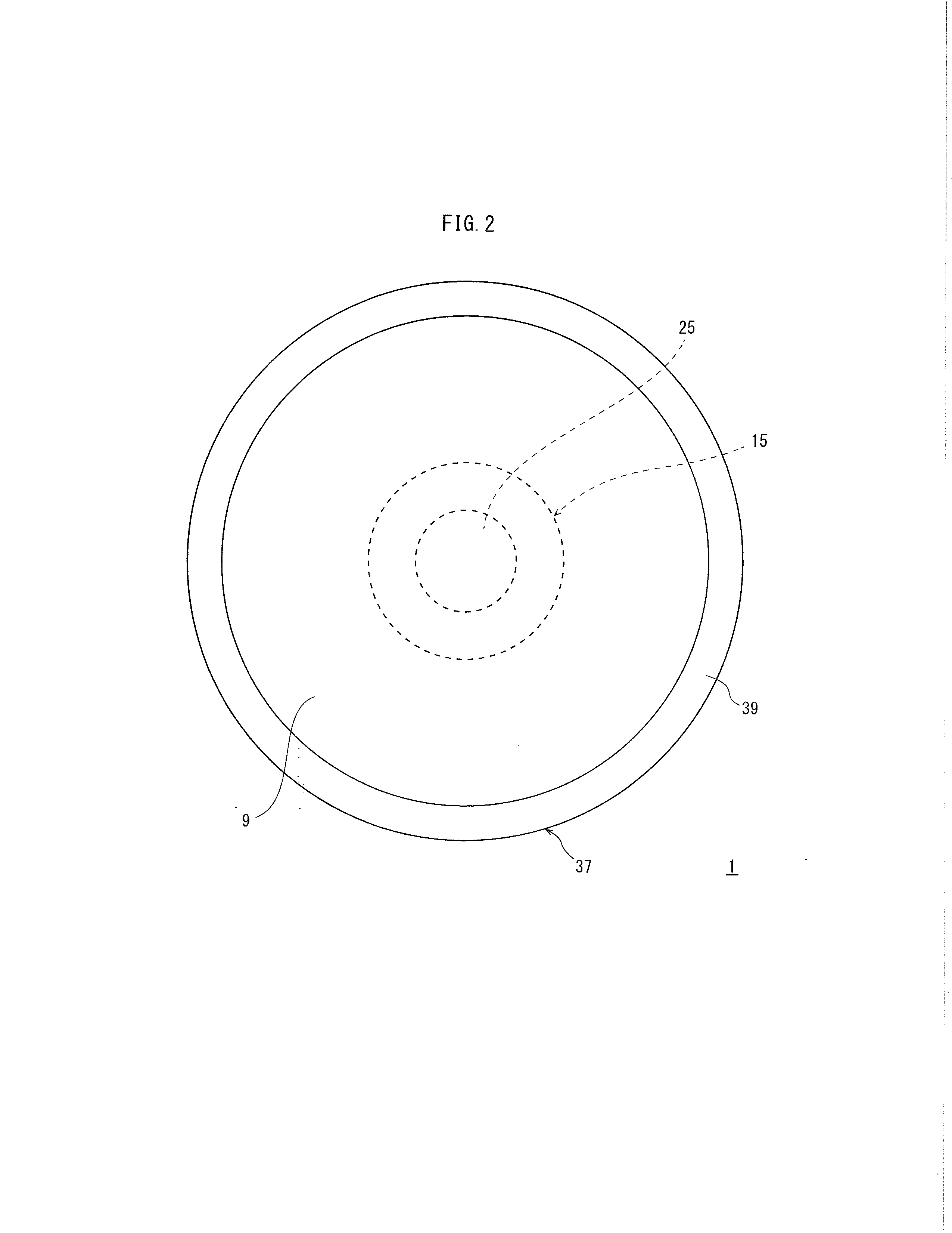
[0046]FIG. 1 is a cross-sectional view showing the structure of an LED lamp 1 according to Embodiment 1. FIG. 2 is a plan view showing the LED lamp 1 viewed from the side opposite a base 13.

[0047]The LED lamp (corresponding to the “lamp” of the present invention) 1 includes an LED module 3, a mount 5, a primary reflective mirror 7, a front plate 9, a circuit unit 11, a base 13, and a circuit case 15. The LED module 3 includes light emitting diodes (LEDs) 23 as light emitters, and is mounted on the mount 5. The primary reflective mirror 7 houses the LED module 3. The front plate 9 is provided at one end (also referred to as “proximal end”) of the primary reflective mirror 7. The circuit unit 11 causes the LEDs 23 to emit light. The base 13 is electrically connected to the circuit unit 11 which is covered by the circuit case 15.

[0048]More specifically, the ...

embodiment 2

[0094]According to Embodiment 1, the LED lamp does not include a light focusing means for focusing light emitted from the LED module 3 to the circuit case 15 disposed in front of the LED module 3 (in the direction in which the LED module 3 emits light). However, an LED lamp according to Embodiment 2 includes a reflector as the light focusing means, so that the light emitted from the LED module 3 can be efficiently reflected on the secondary reflective surface 65 of the circuit case 15 toward the primary reflective mirror 7. Note that the same reference signs are applied to the same elements as in Embodiment 1 described above.

embodiment 2-1

1. Embodiment 2-1

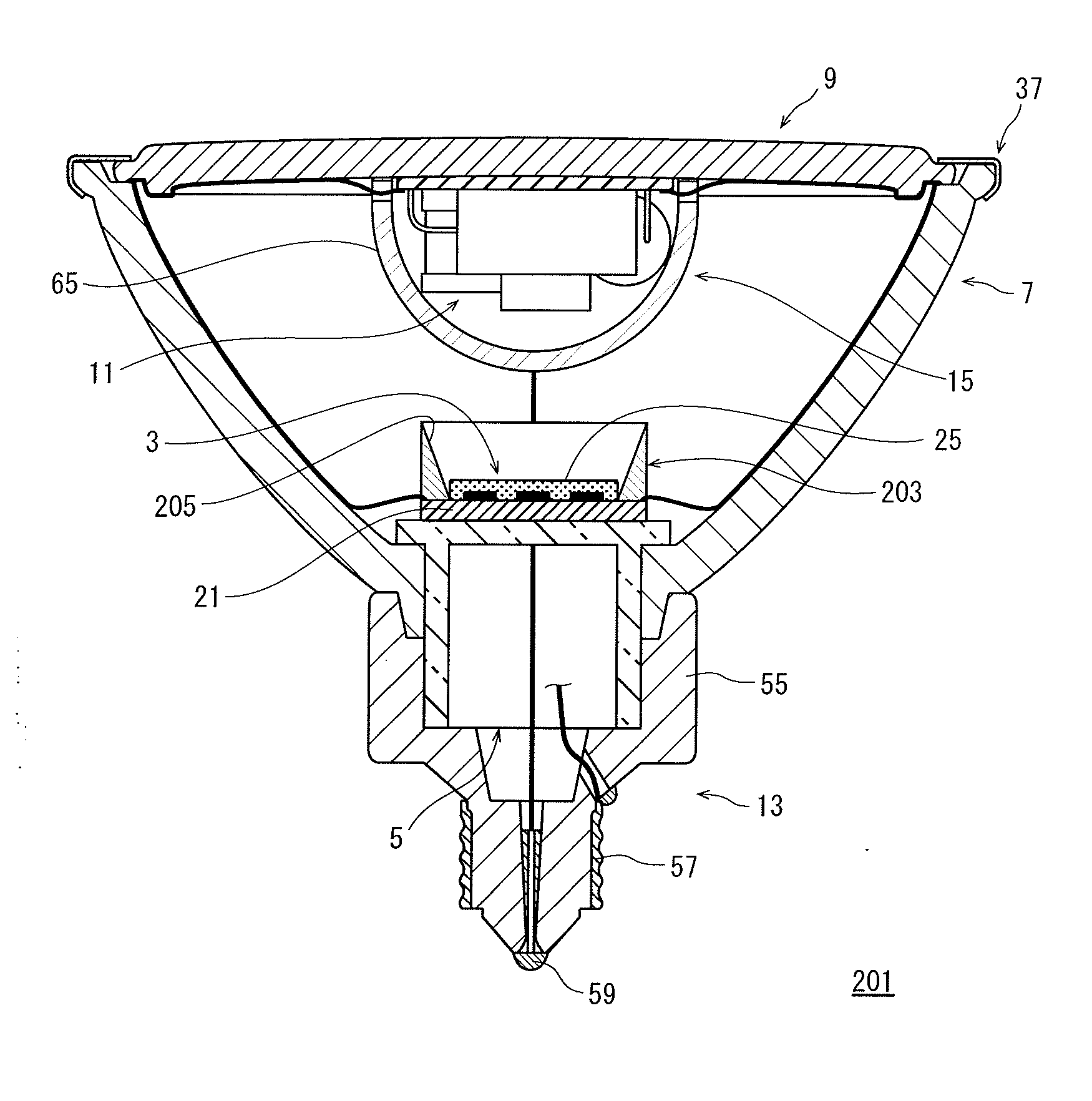
[0095]FIG. 4 is a cross-sectional view showing the structure of an LED lamp 201 according to Embodiment 2-1.

[0096]The LED lamp 201 includes a reflector 203 for reflecting light emitted from the LED module 3 toward the circuit case 15, in addition to the LED module 3, the mount 5, the primary reflective mirror 7, the front plate 9, the circuit unit 11, the base 13, and the circuit case 15. Note that one of the surfaces of the circuit case 15 that faces the LED module 3 is the secondary reflective surface 65.

[0097]In the present embodiment, the reflector 203 has a tubular shape surrounding the sealing member 25 of the LED module 3. The tubular reflector 203 is mounted on the mounting board 21 of the LED module 3, such that the central axis of the reflector 203 coincides with the center of the light emitting portion of the LED module 3.

[0098]The inner peripheral surface of the reflector 203 is inclined and flared, so that the inner diameter of the tubular reflector 203...


PUM


Abstract

A lamp comprises: a primary reflective mirror being funnel-shaped and having an opening at one end; LEDs disposed within the primary reflective mirror; a base attached to another end of the primary reflective mirror; and a circuit configured to receive power via the base and cause the LEDs to emit light. The circuit unit is housed in a circuit case and disposed within the primary reflective mirror close to the opening in a direction in which the LEDs emit light. The circuit case has a secondary reflective surface configured to reflect light emitted from the LEDs to a reflective surface of the primary reflective mirror.

Description

TECHNICAL FIELD[0001]The present invention relates to a lamp, and in particular to a lamp including a reflective mirror and a circuit unit.BACKGROUND ART[0002]In recent years, implementation of high luminance LEDs has triggered an attempt of utilizing a lamp with LEDs as a light source, as a substitute of a halogen light bulb (Patent Literature 1).[0003]Such a lamp using LEDs (hereinafter, simply “LED lamp”) as a substitute of a halogen light bulb has a similar structure to a halogen light bulb, in that the lamp includes a reflective mirror, a plurality of LEDs, a base member, and a circuit unit. The reflective mirror is funnel-shaped and has an opening at one end. The LEDs are provided inside the reflective mirror. The base member is attached to the other end of the reflective mirror, and has a base. The circuit unit receives power via the base, and causes the LEDs to emit light. This circuit unit is stored inside the base member.[0004]The LEDs generate heat when emitting light; ho...

Claims


Application Information

Patent Timeline
Patent Type & Authority Applications(United States)
IPC IPC(8): F21V7/00
CPCF21K9/13F21K9/137F21K9/56F21V7/0033F21V23/006F21V13/04F21Y2101/02F21Y2111/002F21V23/002F21V7/041F21K9/23F21K9/233F21K9/238F21K9/64F21Y2107/10F21Y2115/10
Inventor ISOGAI, TOSHIAKIUEDA, YASUHISASUGITA, KAZUSHIGENAGAI, HIDEOUEMOTO, TAKAARIMIKI, MASAHIROTAKAHASHI, AKIRA
Owner PANASONIC CORP
Learn More