
PCVD Method and Apparatus

Active Publication Date: 2013-07-04
DRAKA COMTEQ BV
View PDF7 Cites 8 Cited by
  • Summary
  • Abstract
  • Description
  • Claims
  • Application Information

AI Technical Summary

Benefits of technology

The patent text describes a process for depositing glass layers on a substrate using a plasma chemical vapor deposition (PCVD) process. The process involves selectively injecting plasma-reactive gas during the deposition process to control deposition and refractive-index oscillations, which can improve the quality and performance of the optical preform produced. An apparatus is also described that minimized any disturbance of the microwave energy from the applicator to the optical preform.

Problems solved by technology

In a subsequent applicator pass, the “thick spots” will generate more heat because of the deposited glass's poor heat conductivity.
This, in turn, leads to even more glass deposition in the subsequent glass layers, which exacerbates the effect of the deposition oscillation.

Method used


Image

  • PCVD Method and Apparatus
  • PCVD Method and Apparatus
  • PCVD Method and Apparatus

Examples


example 1

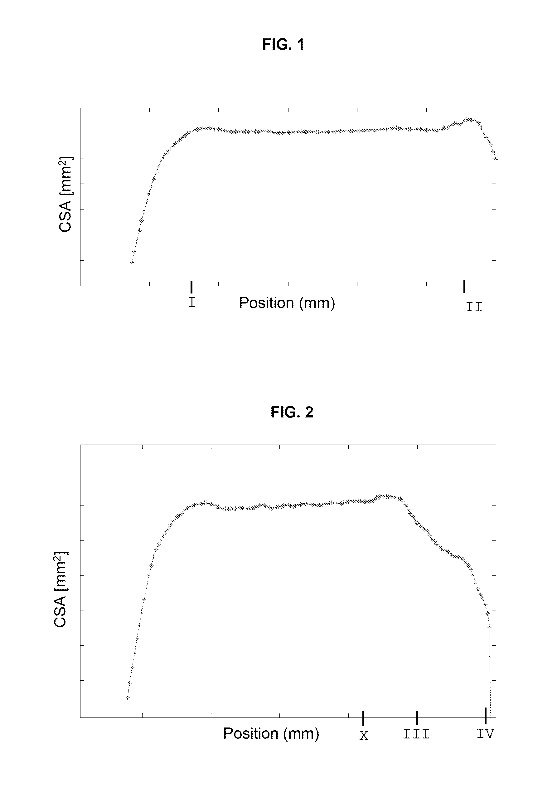
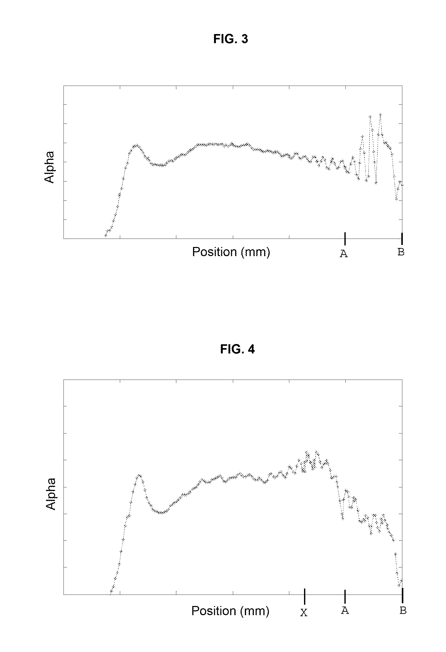
[0119]Another PCVD process was carried out in a PCVD apparatus described in Comparative Example 1 (above), except that one 750-millisecond pulse of oxygen was provided to correspond to an longitudinal position of 1240 millimeters along the substrate tube (referenced by X in FIGS. 2 and 4). The orifice through which the oxygen flowed had an orifice No. 28 (Kv parameter value of 0.011 m3n / hour). The gas pressure was 1.5 bar. The resulting substrate tube was subjected to a contraction process so as to obtain a solid rod (i.e., a primary preform) in the same manner as Comparative Example 1.

[0120]FIG. 2 depicts cross-sectional area (CSA), and FIG. 4 depicts alpha value for the solid rod's core as a function of length (i.e., longitudinal position). FIGS. 2 and 4 illustrate effects of the present invention. For instance, FIG. 4 shows substantially reduced alpha-value variation over length of the glass rod as compared to the extreme alpha oscillations shown in FIG. 3 (i.e., between position...

example 2

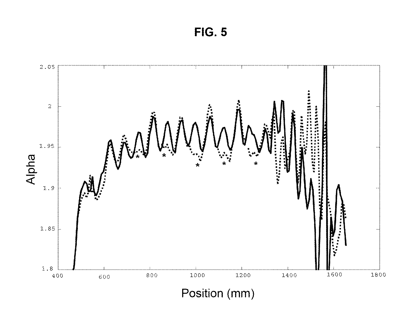
[0121]Another PCVD process was carried out in a PCVD apparatus described in Comparative Example 1 (above), except that five 50-millisecond pulses of 5 percent Freon and 95 percent oxygen were provided to correspond to longitudinal positions of 1240 millimeters and repeated at 1140 millimeters, 1020 millimeters, 900 millimeters, 780 millimeters, and 660 millimeters, respectively, along the substrate tube. These longitudinal positions are referenced by asterisks (*) in FIG. 5.

[0122]The orifice through which the plasma-reactive gas flowed had an orifice No. 28 (Kv parameter value of 0.011 m3n / hour). The gas pressure was 1.8 bar. The resulting substrate tube was subjected to a contraction process so as to obtain a solid rod (i.e., a primary preform) in the same manner as Comparative Example 1.

[0123]To supplement the present disclosure, this application incorporates entirely by reference the following commonly assigned patents, patent application publications, and patent applications: U....


PUM

PropertyMeasurementUnit
Timeaaaaaaaaaa
Timeaaaaaaaaaa
Timeaaaaaaaaaa

Abstract

The disclosed Plasma Chemical Vapor Deposition (PCVD) process uses the injection of plasma-reactive gas to control deposition oscillation and refractive-index oscillation (e.g., alpha oscillation). This PCVD process, which may employ a modified PCVD apparatus, achieves more uniform glass deposition. This, in turn, results in optical preforms and optical fibers having more uniform optical properties.

Description

CROSS-REFERENCE TO PRIORITY APPLICATION[0001]This application hereby claims the benefit of pending Dutch Application No. 2007831 (filed Nov. 21, 2011, at the Dutch Patent Office), which is hereby incorporated by reference in its entirety.FIELD OF THE INVENTION[0002]The present invention relates to the field of Plasma Chemical Vapor Deposition (PCVD).BACKGROUND[0003]Plasma-enhanced chemical vapor deposition (PECVD or PCVD) is a process used to deposit thin films from a gaseous state (vapor) to a solid state. In the PCVD process, chemical reactions occur after creation of a plasma of the reacting gases.[0004]Generally, in the field of optical fibers, multiple thin films of glass (e.g., glass layers) are deposited on the inside surface of a substrate tube. Glass-forming gases (e.g., doped or undoped reactive gases) are introduced into the interior of the substrate tube from one end (i.e., the supply side of the substrate tube). Doped or undoped glass layers are deposited onto the inter...

Claims


Application Information

Patent Timeline
IPC IPC(8): C03B37/014
CPCC03B37/0183C23C16/045C03B19/143C23C16/511C03B37/01413C23C16/45523C03B37/018C03B2207/36C03B2207/66C03B2207/70
Inventor MILICEVIC, IGORVAN STRALEN, MATTHEUS JACOBUS NICOLAASHARTSUIKER, JOHANNES ANTOON
Owner DRAKA COMTEQ BV
Learn More