
Systems and Methods Using External Heater Systems in Microfluidic Devices

a heater system and microfluidic technology, applied in the field of heater systems for microfluidic devices, can solve the problems of limited throughput and poor reproducibility, and achieve the effects of limiting heat losses, improving temperature uniformity, and limiting heat losses

Active Publication Date: 2013-06-20
CANON USA
View PDF5 Cites 31 Cited by
  • Summary
  • Abstract
  • Description
  • Claims
  • Application Information

AI Technical Summary

Benefits of technology

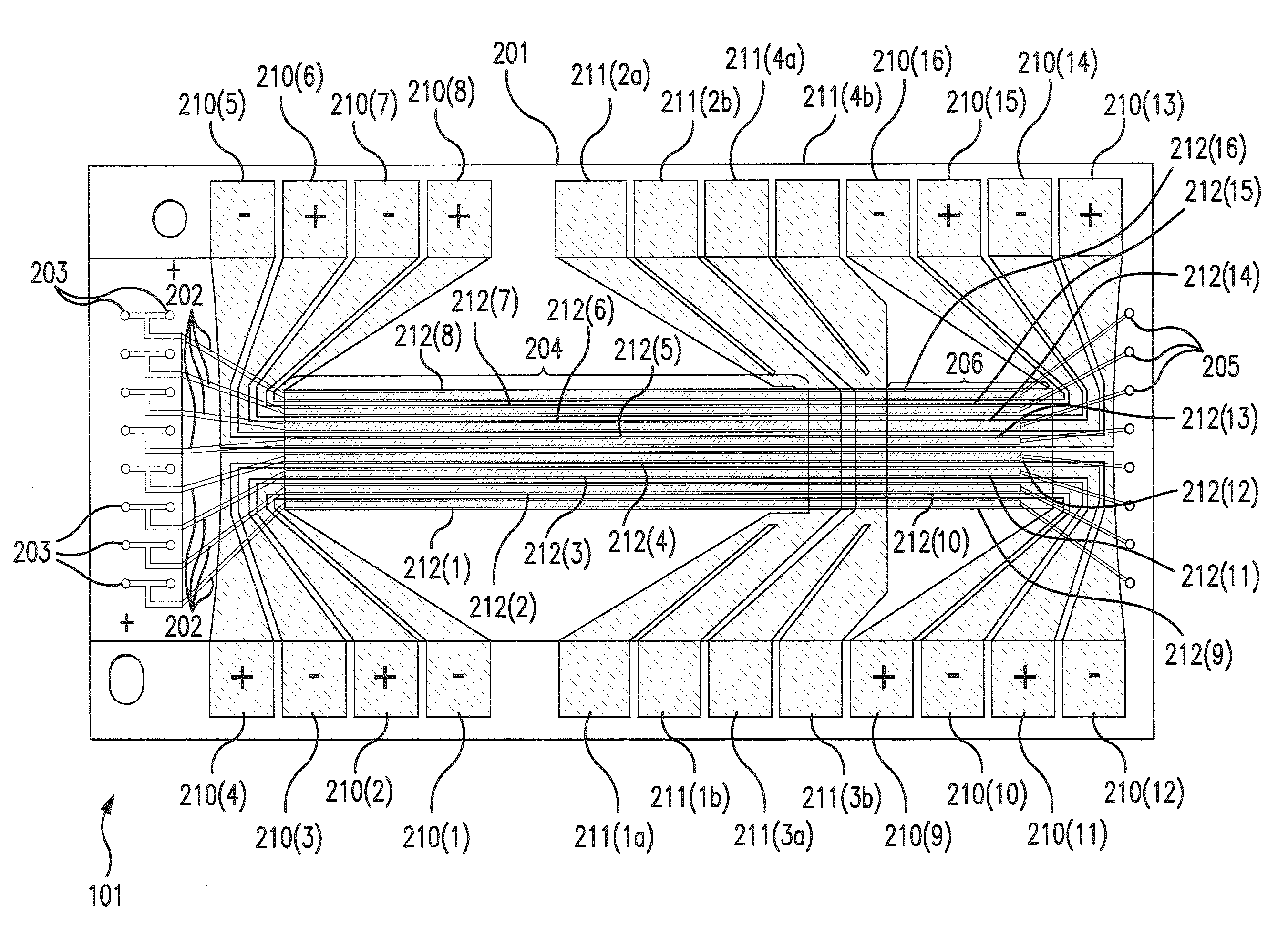
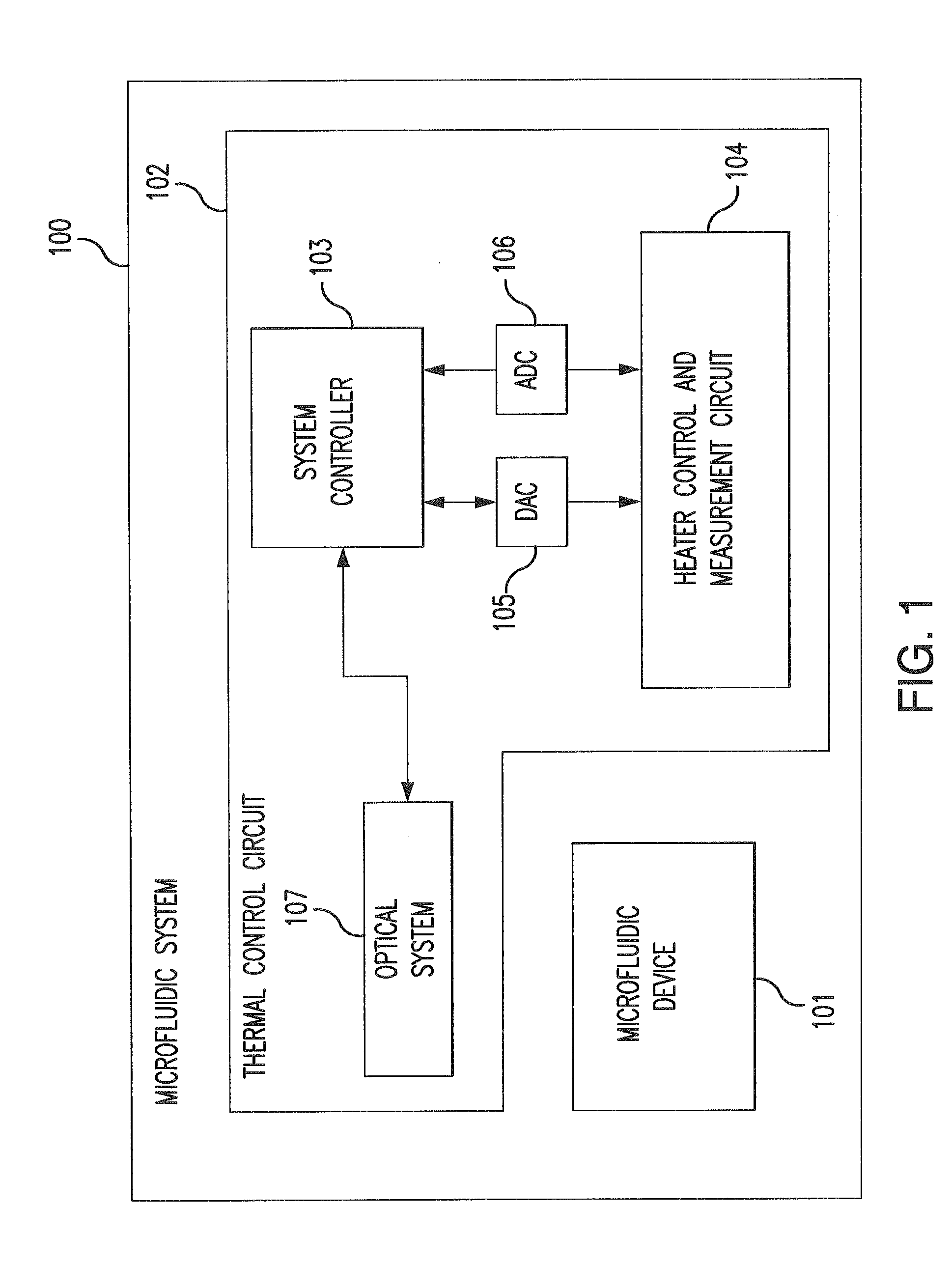
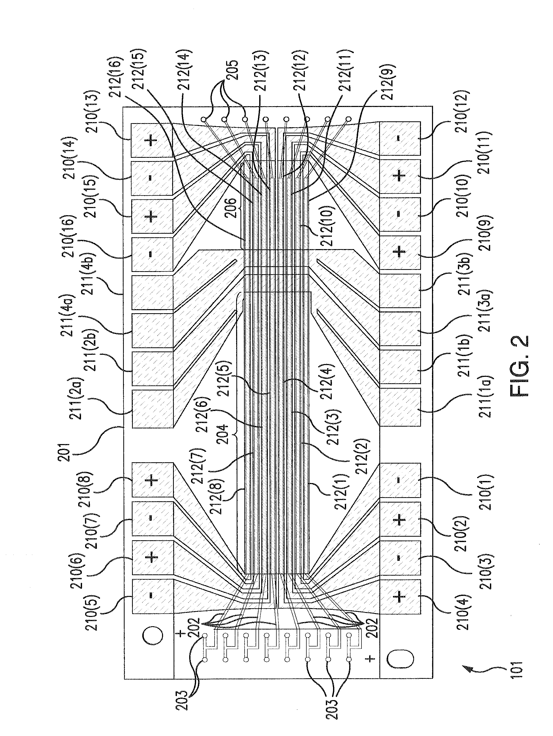
This patent describes a system that can adjust the temperature of a heat spreader and fluidic channels or reservoirs using a cooling system. The cooling system can limit heat loss from samples in the fluidic channels and improve temperature uniformity by reducing heat losses. In one embodiment, the cooling system is a PWM fan or blower. Overall, this technology helps to maintain accurate temperature measurements and ensures the samples are protected from damage.

Problems solved by technology

Throughput is limited by the size of the heater block which holds a fixed number of patient samples and is slow to heat.
Reproducibility also suffers when heating blocks are large due to non-uniformity of temperature.

Method used


Image

  • Systems and Methods Using External Heater Systems in Microfluidic Devices
  • Systems and Methods Using External Heater Systems in Microfluidic Devices
  • Systems and Methods Using External Heater Systems in Microfluidic Devices

Examples


examples

[0107]Thermal uniformity and stability of melt temperatures

[0108]Run Conditions and Cartridge Performance

[0109]The uniformity of temperature and the stability of the melt were assessed by running a 17 melt long panel on four microfluidic cartridges featuring the heat spreader and external heater. The panel alternated between UCE17 and the 2C9*3 assays (9 melts of UCE17 and 8 of 2C9*3 in total). Two assays were used to have some comparison between the stability and uniformity of the two different targets. Multiple melts of the same two assays was useful for determining statistics as well as drift over time.

[0110]PCR reagents (Blanking solution, DNA sample buffer, *3 primer, UCE17 primer, Polymerase, RFCal and CULS buffer) were automixed by the instrument. PCR was performed, followed by thermal melting. Conditions for the PCR and thermal melt were: 95° C. for 2 s including a 0.25 s ramp up transition; 55° C. for 1.5 s including a 0.25 s ramp down transition; and 72° C. for 6.5 s inclu...


PUM

PropertyMeasurementUnit
Massaaaaaaaaaa
Temperatureaaaaaaaaaa
Pressureaaaaaaaaaa

Abstract

The present invention relates to methods and systems that result in high quality, reproducible, thermal melt analysis on a microfluidic platform. The present invention relates to methods and systems using thermal systems including heat spreading devices, including interconnection methods and materials developed to connect heat spreaders to microfluidic devices. The present invention also relates to methods and systems for controlling, measuring, and calibrating the thermal systems of the present invention.

Description

CROSS REFERENCE TO RELATED APPLICATIONS[0001]This application claims the benefit of U.S. Provisional Patent Application Ser. Nos. 61 / 487,269, 61 / 487,081, and 61 / 487,069, all of which were filed May 17, 2011, the contents of which are incorporated herein by reference in their entirety.[0002]Reference is also made to the following U.S. patents and applications, each of which are incorporated herein in their entirety: U.S. Pat. No. 7,943,320 issued May 17, 2011 entitled “Unsymmetrical Cyanine Dyes for High Resolution Nucleic Acid Melting Analysis, U.S. patent application Ser. No. 11 / 352,452, entitled “Method and apparatus for generating thermal melting curves in a microfluidic device” published Feb. 1, 2007 as US 2007 / 0026421, U.S. patent application Ser. No. 11 / 381,896 entitled “Method and Apparatus for Applying Continuous Flow and Uniform Temperature to Generate Thermal Melting Curves in a Microfluidic Device” published Oct. 4, 2007 as US 2007 / 0231799, U.S. patent application Ser. No...

Claims


Application Information

Patent Timeline
IPC IPC(8): H05B1/02F25B29/00
CPCH05B1/0297F25B29/00B01L3/5027B01L7/52B01L2300/1827Y10T436/143333B01L2200/148B01L2300/0816B01L2300/1844B01L2300/1894B01L2200/147
Inventor COURSEY, JOHNATHAN S.HASSON, KENTON C.
Owner CANON USA
Learn More