
Spindle motor

a spindle motor and spindle body technology, applied in the direction of supports/enclosements/casings, dynamo-electric machines, instruments, etc., can solve the problems of weak rigidity of bearings, and affecting the rigidity of hubs according to the related ar

Inactive Publication Date: 2013-06-20
SAMSUNG ELECTRO MECHANICS CO LTD
View PDF9 Cites 2 Cited by
  • Summary
  • Abstract
  • Description
  • Claims
  • Application Information

AI Technical Summary

Benefits of technology

The present invention provides a spindle motor that can improve its performance and lifespan by preventing the position of a stopper from being changed while improving the rigidity of a bearing. This prevents the shaft from overfloating and ensures the motor operates efficiently.

Problems solved by technology

In this case, an axial length of the sleeve is relatively short, due to a space occupied by the stopper, such that a rigidity of a bearing may be weak.
Further, in the case that an external impact is applied to the spindle motor, the stopper structure according to the related art may not be able to maintain the rigidity of a hub, such that the hub may be separated from the shaft.

Method used


Image

  • Spindle motor
  • Spindle motor
  • Spindle motor

Examples


Embodiment Construction

[0029]Hereinafter, embodiments of the present invention will be described in detail with reference to the accompanying drawings. The invention may, however, be embodied in many different forms and should not be construed as being limited to the embodiments set forth herein. Rather, these embodiments are provided so that this disclosure will be thorough and complete, and will fully convey the scope of the invention to those skilled in the art.

[0030]In the drawings, the shapes and dimensions of elements may be exaggerated for clarity, and the same reference numerals will be used throughout to designate the same or like elements.

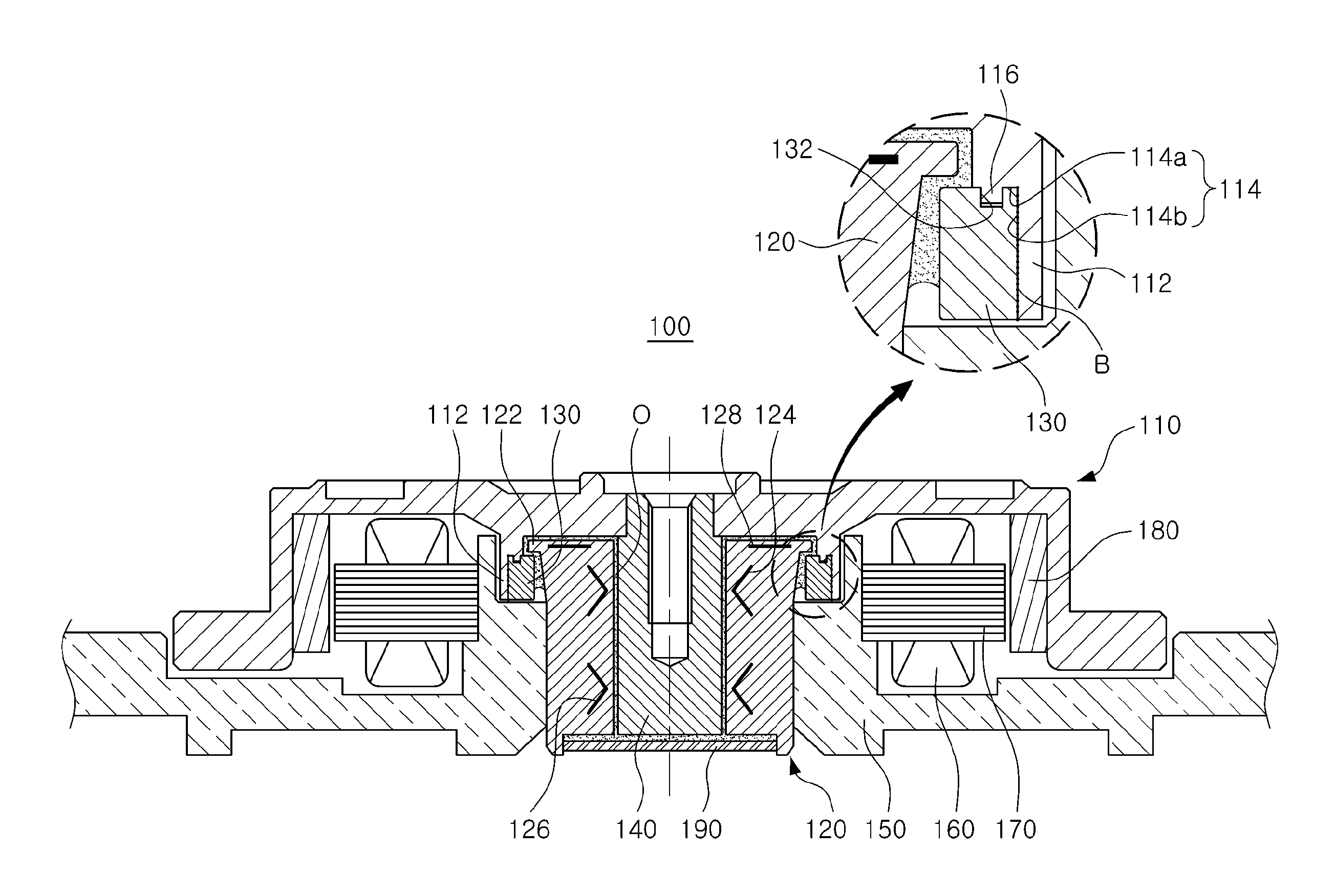
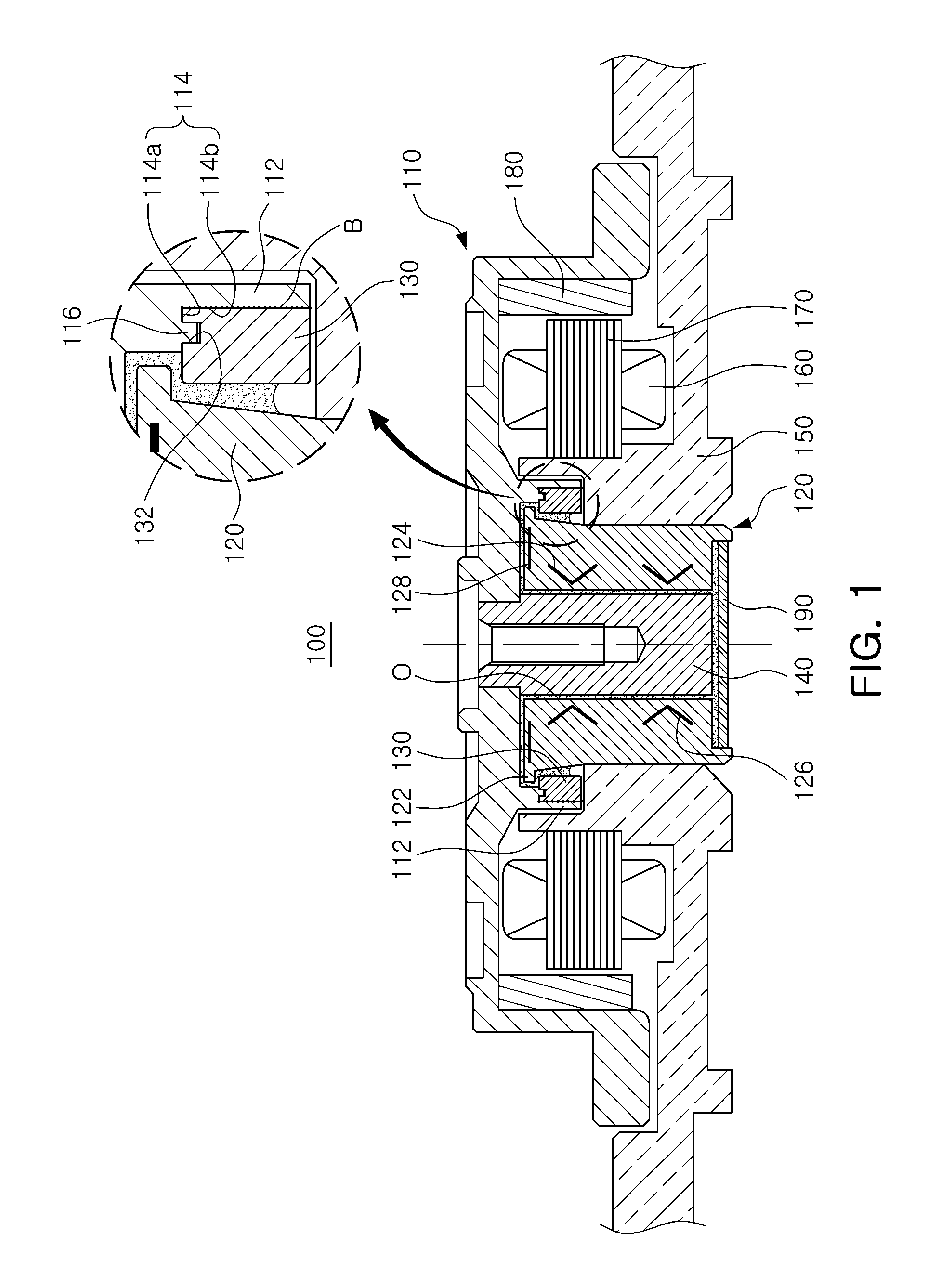
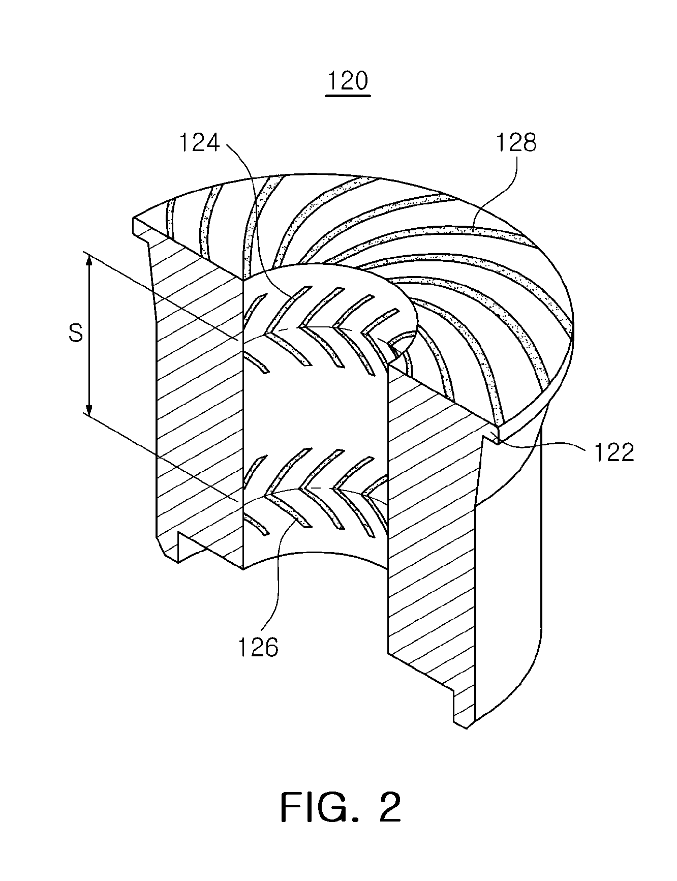
[0031]FIG. 1 is a schematic cross-sectional view illustrating a spindle motor according to an embodiment of the present invention, FIG. 2 is a schematic cut-away perspective view illustrating a sleeve provided in a spindle motor according to the embodiment of the present invention, and FIG. 3 is a schematic exploded cut-away perspective view illustrating a hub ...


PUM


Abstract

There is provided a spindle motor, including: a hub rotated together with a shaft; a sleeve supporting rotation of the shaft via oil; and a stopper mounted on the hub to prevent the hub from overfloating with respect to the sleeve, wherein one of opposing surfaces of the stopper and the hub is provided with at least one press-fitting groove for press-fitting the stopper in the hub, and the other of the opposing surfaces of the stopper and the hub is provided with at least one press-fitting protrusion press-fitted to the press-fitting groove.

Description

CROSS-REFERENCE TO RELATED APPLICATIONS[0001]This application claims the priority of Korean Patent Application No. 10-2011-0135257 filed on Dec. 15, 2011, in the Korean Intellectual Property Office, the disclosure of which is incorporated herein by reference.BACKGROUND OF THE INVENTION[0002]1. Field of the Invention[0003]The present invention relates to a spindle motor, and more particularly, to a spindle motor that may be applied to a hard disk drive (HDD) rotating a recording disk.[0004]2. Description of the Related Art[0005]A hard disk drive (HDD), an information storage device, is a device that reads data stored on a disk or writes data to a disk, using a read / write head.[0006]The hard disk drive requires a disk driving apparatus capable of driving a disk, and in the disk driving apparatus, a spindle motor is commonly used.[0007]The spindle motor uses a fluid dynamic bearing in which a shaft is supported by fluid pressure generated in oil interposed between the shaft, a rotating...

Claims


Application Information

Patent Timeline
Patent Type & Authority Applications(United States)
IPC IPC(8): H02K5/16
CPCH02K5/163H02K5/165G11B19/20
Inventor SONG, SANG JAE
Owner SAMSUNG ELECTRO MECHANICS CO LTD
Learn More