
Control apparatus for hybrid vehicle, hybrid vehicle, and control method for hybrid vehicle

a control apparatus and hybrid technology, applied in the direction of electric control, ignition automatic control, instruments, etc., can solve the problems of reducing the efficiency of catalyst rapid warm-up, and increasing the fuel pressure for injecting catalyst fuel into the cylinder, so as to reduce the influence of the fluctuation of the amount of in-cylinder injection

Active Publication Date: 2013-06-13
TOYOTA JIDOSHA KK
View PDF5 Cites 23 Cited by
  • Summary
  • Abstract
  • Description
  • Claims
  • Application Information

AI Technical Summary

Benefits of technology

The patent text describes a method to prevent fluctuations in air-fuel ratio when an internal combustion engine is restarted after a temporary stop. This is achieved by initially operating the engine only by port injection and then starting in-cylinder injection when the fuel pressure reaches the reference level. This method ensures a reliable catalytic converter warm-up and sufficient exhaust gas purification performance.

Problems solved by technology

However, in the control apparatus for a hybrid vehicle described above, the internal combustion engine is intermittently driven and the frequency of repetition of driving and stopping becomes relatively high.
As a result, when the internal combustion engine is restarted after the temporary stop due to the intermittent operation, there has been a possibility that the fuel pressure increase for injecting the fuel required for the catalyst rapid warm-up into the cylinder is retarded.
With the retardation, there has been a possibility that a fluctuation in air-fuel ratio (what is called an air-fuel ratio variation) or an interruption of the in-cylinder injection is caused and the catalyst rapid warm-up is adversely affected.
As a result, similarly to the above case, there has been a possibility that the catalyst rapid warm-up is adversely affected.

Method used


Image

  • Control apparatus for hybrid vehicle, hybrid vehicle, and control method for hybrid vehicle
  • Control apparatus for hybrid vehicle, hybrid vehicle, and control method for hybrid vehicle
  • Control apparatus for hybrid vehicle, hybrid vehicle, and control method for hybrid vehicle

Examples


Embodiment Construction

[0025]Hereinbelow, an embodiment of the invention will be described with reference to the drawings.

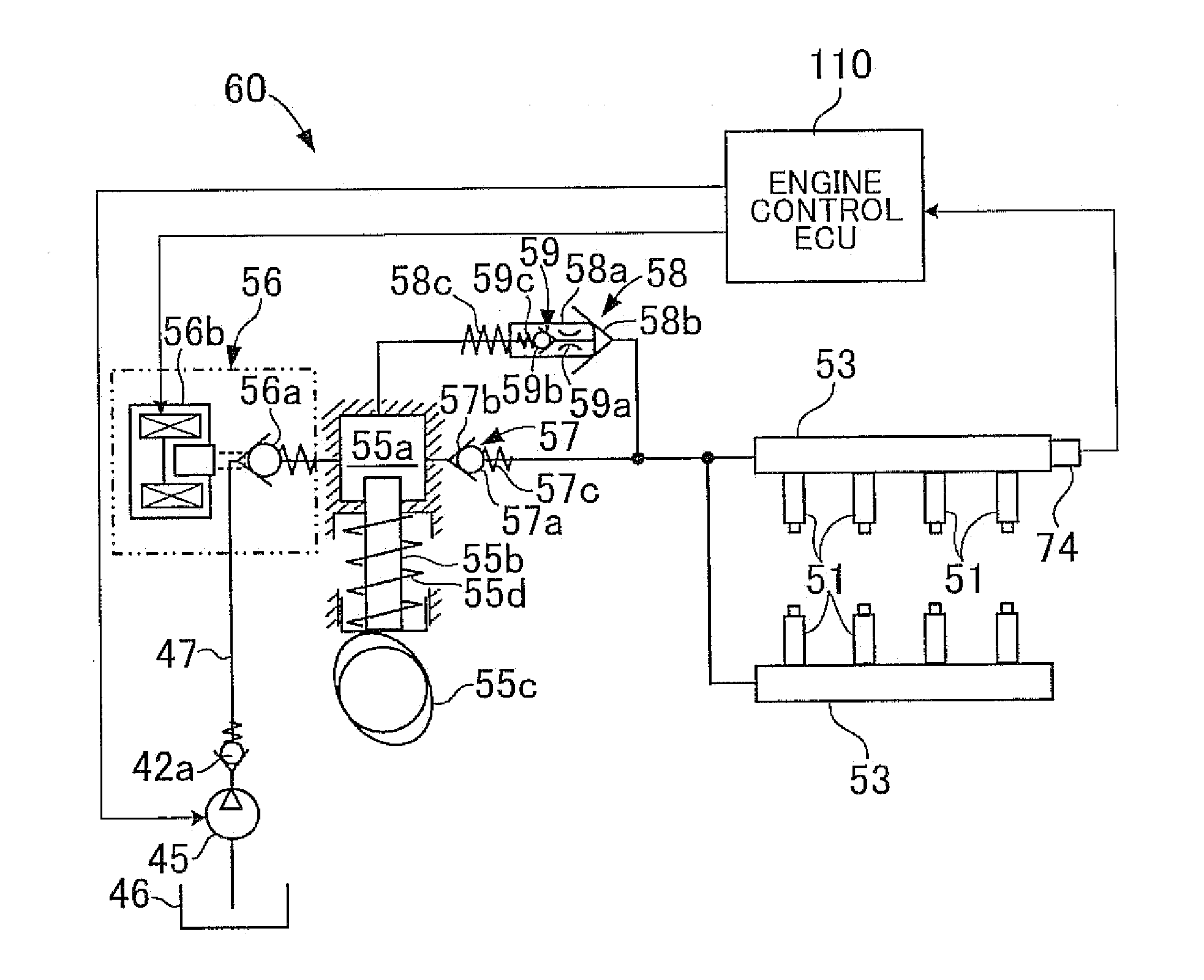
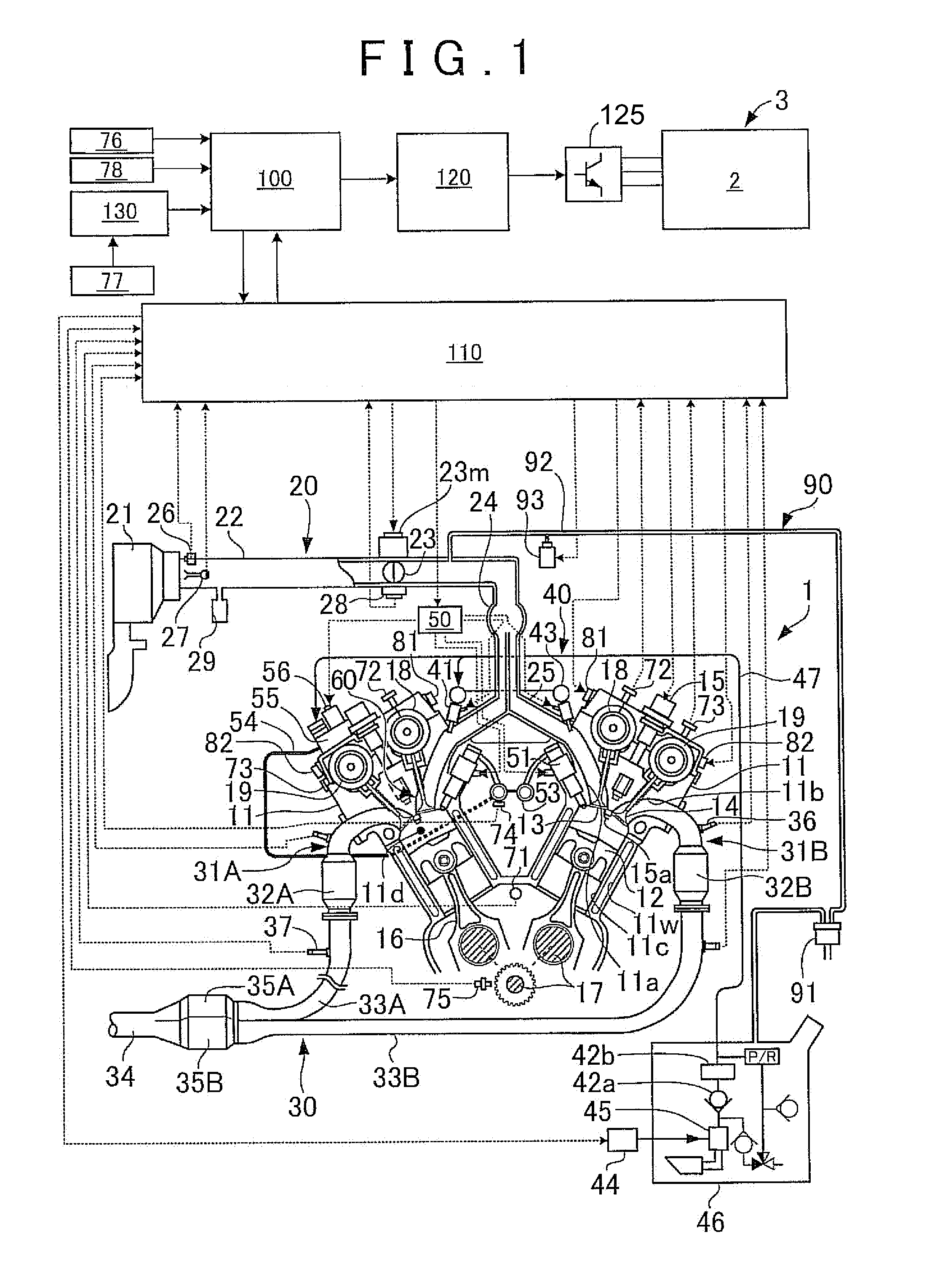
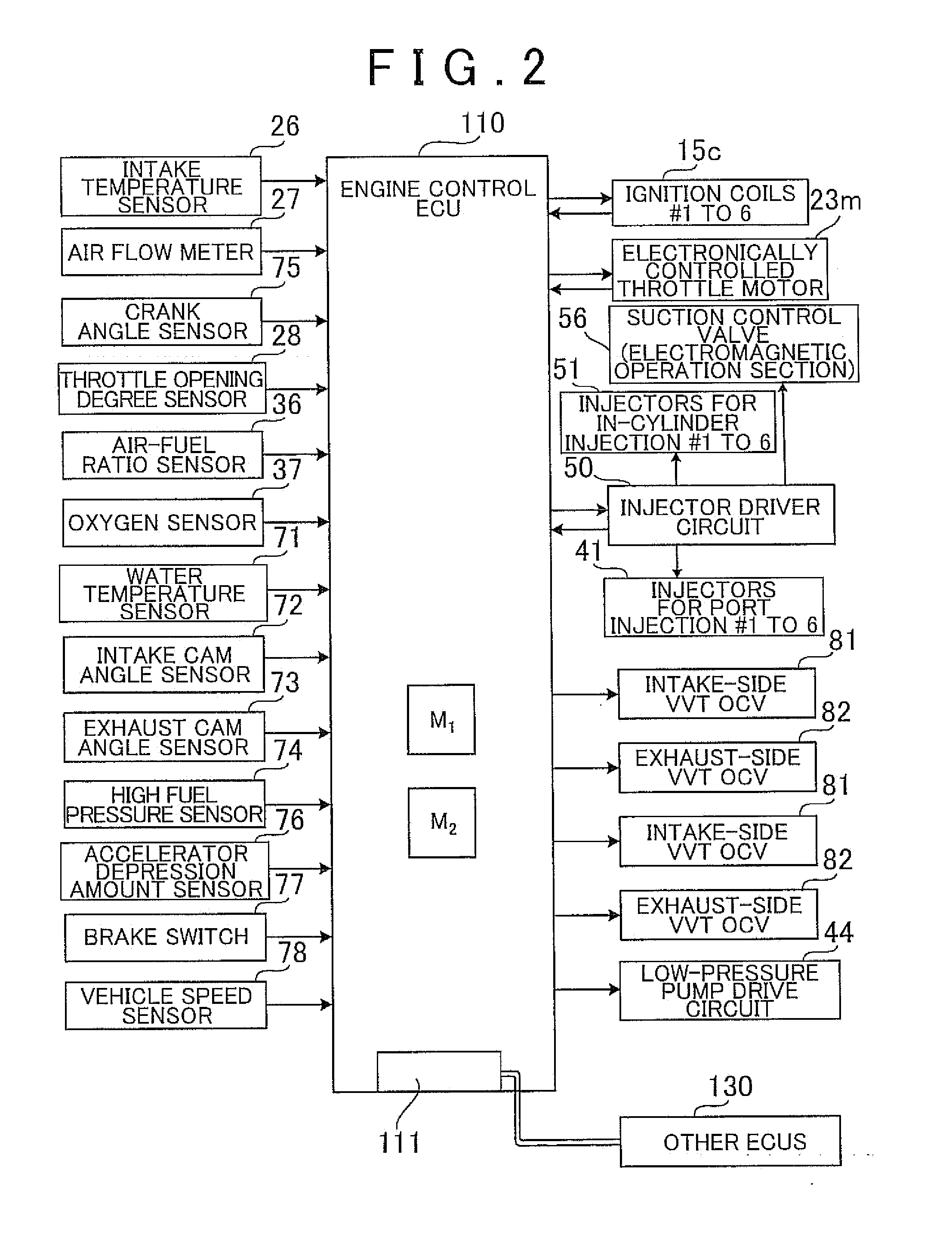
[0026]FIGS. 1 to 3 show schematic configurations of a running driving source of a hybrid vehicle and its control apparatus according to the embodiment of the invention. FIGS. 4 to 6 show the outline of an injection control at the time of restart of an internal combustion engine by the control apparatus.

[0027]The hybrid vehicle of the embodiment is an automobile on which a hybrid drive system using an internal combustion engine and a generator-motor in combination is mounted as the running drive source. The internal combustion engine mounted on the hybrid vehicle of the embodiment adopts a dual injection system in order to respond to high-level requests for improvements in the fuel efficiency and output of the running drive source and the exhaust gas purification performance of the hybrid vehicle. In the dual injection system, a fuel injection valve for port injection and a fuel injecti...


PUM


Abstract

An intermittent operation control is executed, wherein a hybrid vehicle is run with a running drive source while an internal combustion engine is intermittently operated in the intermittent operation control. When the internal combustion engine is restarted after a stop due to the intermittent operation control, a rapid warm-up control is executed in which a catalytic converter is rapidly warmed up by retarding the ignition timing of the internal combustion engine. In addition, when the internal combustion engine is restarted, the internal combustion engine is operated only by port injection until the pressure of fuel for in-cylinder injection reaches a reference set pressure. Subsequently, when the pressure of the fuel for in-cylinder injection reaches the reference set pressure, the in-cylinder injection is started.

Description

INCORPORATION BY REFERENCE[0001]The disclosure of Japanese Patent Application No. 2011-269205 filed on Dec. 8, 2011 including the specification, drawings and abstract is incorporated herein by reference in its entirety.BACKGROUND OF THE INVENTION[0002]1. Field of the Invention[0003]The invention relates to a control apparatus for a hybrid vehicle, a hybrid vehicle, and a control method for a hybrid vehicle, in which, of an internal combustion engine and a motor, the internal combustion engine is configured to be intermittently operated.[0004]2. Description of Related Art[0005]In an internal combustion engine mounted on a vehicle, conventionally in-cylinder injection, i.e., direct fuel injection into a cylinder is finely controlled and port injection is used in combination. Fuel efficiency, an output, and combustion stability during a warm-up are improved by controlling the in-cylinder injection and the port injection. In such an internal combustion engine, the combustion in the cyli...

Claims


Application Information

Patent Timeline
IPC IPC(8): B60W20/00B60W10/08B60W30/18B60W10/06
CPCB60W20/00F02P5/045B60W10/08B60W30/18Y10S903/93F02D41/0255F02D41/062F02D41/3094F02N11/0814F02P5/1506F02D2200/0602B60W30/194F02D37/02B60Y2300/474B60W20/1082Y02T10/26B60W10/06B60W20/16Y02T10/12
Inventor FUKUZAWA, NAOYA
Owner TOYOTA JIDOSHA KK
Learn More