Radar apparatus
a technology of radar and distance measurement, applied in the field of radar equipment, can solve the problems of reducing the distance measurement accuracy of targets trb>1/b>-trb>3, and achieve the effect of increasing the measurement distance rang
- Summary
- Abstract
- Description
- Claims
- Application Information
AI Technical Summary
Benefits of technology
Problems solved by technology
Method used
Image
Examples
embodiment 1
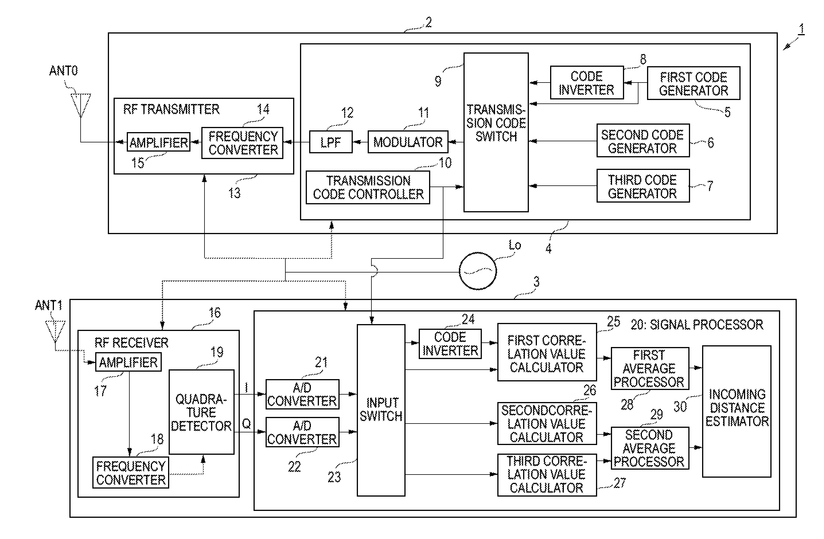
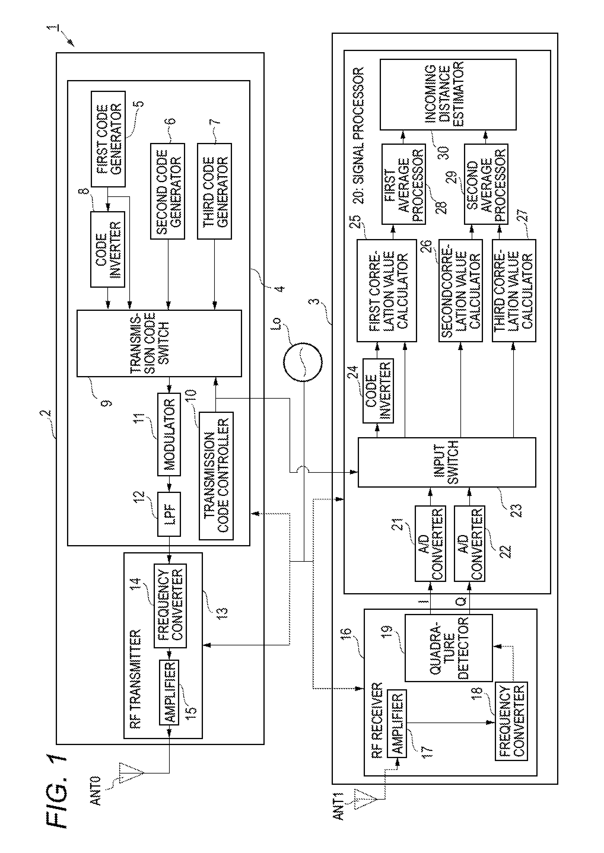
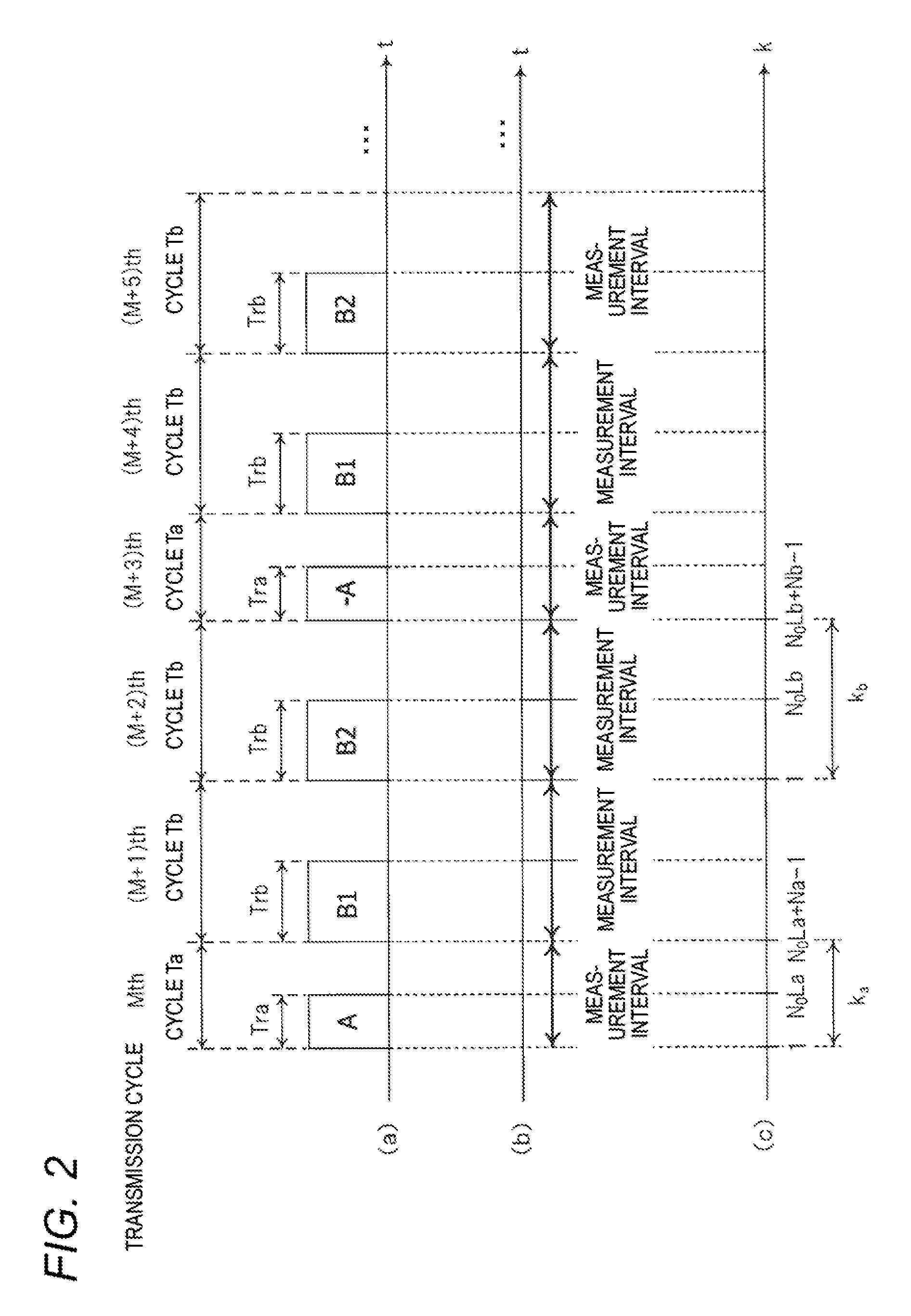
[0050]The configuration and operation of a radar apparatus 1 according to a first embodiment will be described with reference to FIGS. 1 and 2. FIG. 1 is a block diagram showing the internal configuration of the radar apparatus 1 according to the first embodiment. FIG. 2 is a timing chart illustrating how the radar apparatus 1 according to the first embodiment operates. FIG. 2(a) is an explanatory diagram showing transmission cycles Ta, transmission cycles Tb, and transmission codes used in the respective transmission cycles. FIG. 2(b) is an explanatory diagram showing measurement intervals. FIG. 2(c) is an explanatory diagram showing relationships between transmission cycles Ta and Tb and discrete times ka and kb, respectively.
[0051]As shown in FIG. 1, the radar apparatus 1 is configured so as to include a reference oscillator Lo, a radar transmitter 2 to which a transmission antenna ANT0 is connected, and a radar receiver 3 to which a reception antenna ANT1 is connected. The radar...
modification 1
[Modification 1 of Embodiment 1]
[0130]The first embodiment is directed to the case that the parameter Za which is an integer by which the transmission cycle Ta is to be multiplied and the parameters Zb1 and Zb2 which are integers by which the transmission cycle Tb is to be multiplied are all equal to 1. That is, the first embodiment is directed to the case that as shown in FIG. 2 the transmission code A is used in the Mth transmission cycle (transmission cycle Ta), the transmission code B1 is used in the (M+1)th transmission cycle (transmission cycle Tb), and the transmission code B2 is used in the (M+2)th transmission cycle (transmission cycle Tb).
[0131]A first modification of the first embodiment is directed to a case that each of the parameters Za, Zb1, and Zb2 is not equal to 1 but equal to a natural number that is larger than or equal to 2.
[0132]More specifically, after a high-frequency transmission signal generated according to the transmission code A is transmitted in an Mth ...
embodiment 2
[0141]Next, the configuration and operation of a radar apparatus 1b according to a second embodiment will be described with reference to FIGS. 5 and 6. FIG. 5 is a block diagram showing the internal configuration of the radar apparatus 1B according to the second embodiment. FIG. 6 is a timing chart illustrating how the radar apparatus 1b according to the second embodiment operates. FIG. 6(a) is an explanatory diagram showing transmission cycles Ta, transmission cycles Tb, and transmission codes used in the respective transmission cycles. FIG. 6(b) is an explanatory diagram showing measurement intervals. FIG. 6(c) is an explanatory diagram showing relationships between transmission cycles Ta and Tb and discrete times ka and kb, respectively.
[0142]In the following description of the second embodiment, parts of the configuration and operation that are different than in the first embodiment will be described and the same parts of the configuration and operation as in the first embodimen...
PUM
 Abstract
Description
Claims
Application Information
 - R&D
- Intellectual Property
- Life Sciences
- Materials
- Tech Scout
- Unparalleled Data Quality
- Higher Quality Content
- 60% Fewer Hallucinations
Browse by: Latest US Patents, China's latest patents, Technical Efficacy Thesaurus, Application Domain, Technology Topic, Popular Technical Reports.
© 2025 PatSnap. All rights reserved.Legal|Privacy policy|Modern Slavery Act Transparency Statement|Sitemap|About US| Contact US: help@patsnap.com


