
Image forming apparatus capable of reducing jam in fixing unit

a technology of fixing unit and forming apparatus, which is applied in the direction of electrographic process apparatus, instruments, optics, etc., can solve the problems of paper jam, paper jam, paper jam, etc., and achieve the effect of increasing the white space siz

Inactive Publication Date: 2013-05-30
RICOH KK
View PDF0 Cites 17 Cited by
  • Summary
  • Abstract
  • Description
  • Claims
  • Application Information

AI Technical Summary

Benefits of technology

The patent text describes an image forming apparatus that can control the size of white space (unencrypted) on a recording medium and adjust its target fixing temperature based on the number of recording media processed. This ensures consistent and high-quality printing, regardless of the size of the recording medium. The apparatus also includes a recording medium counter to count the number of recording media processed and a size control unit to adjust the white space size accordingly. The target fixing temperature is decreased when the number of recording media exceeds a predetermined number. This technology helps to improve the efficiency and accuracy of image printing.

Problems solved by technology

But such fixing units have the following problem.
Therefore, movement of the tip of the paper is in an unstable state.
Especially, because thin paper is soft, thin paper is easily adhered to the fixing member and a paper jam occurs often.
The thin paper is adhered to the fixing member or the pressure member by toner, wrapped around the fixing member or the pressure member, and a paper jam occurs.
However, when the separating claw is used, the problems related to the separating claw occur.
Moreover, this technology does not consider time degradation.
As time goes on, the wrapping jam occurs more frequently.
So, even in this technology, there is probability that the wrapping jam occurs.

Method used


Image

  • Image forming apparatus capable of reducing jam in fixing unit
  • Image forming apparatus capable of reducing jam in fixing unit
  • Image forming apparatus capable of reducing jam in fixing unit

Examples


Embodiment Construction

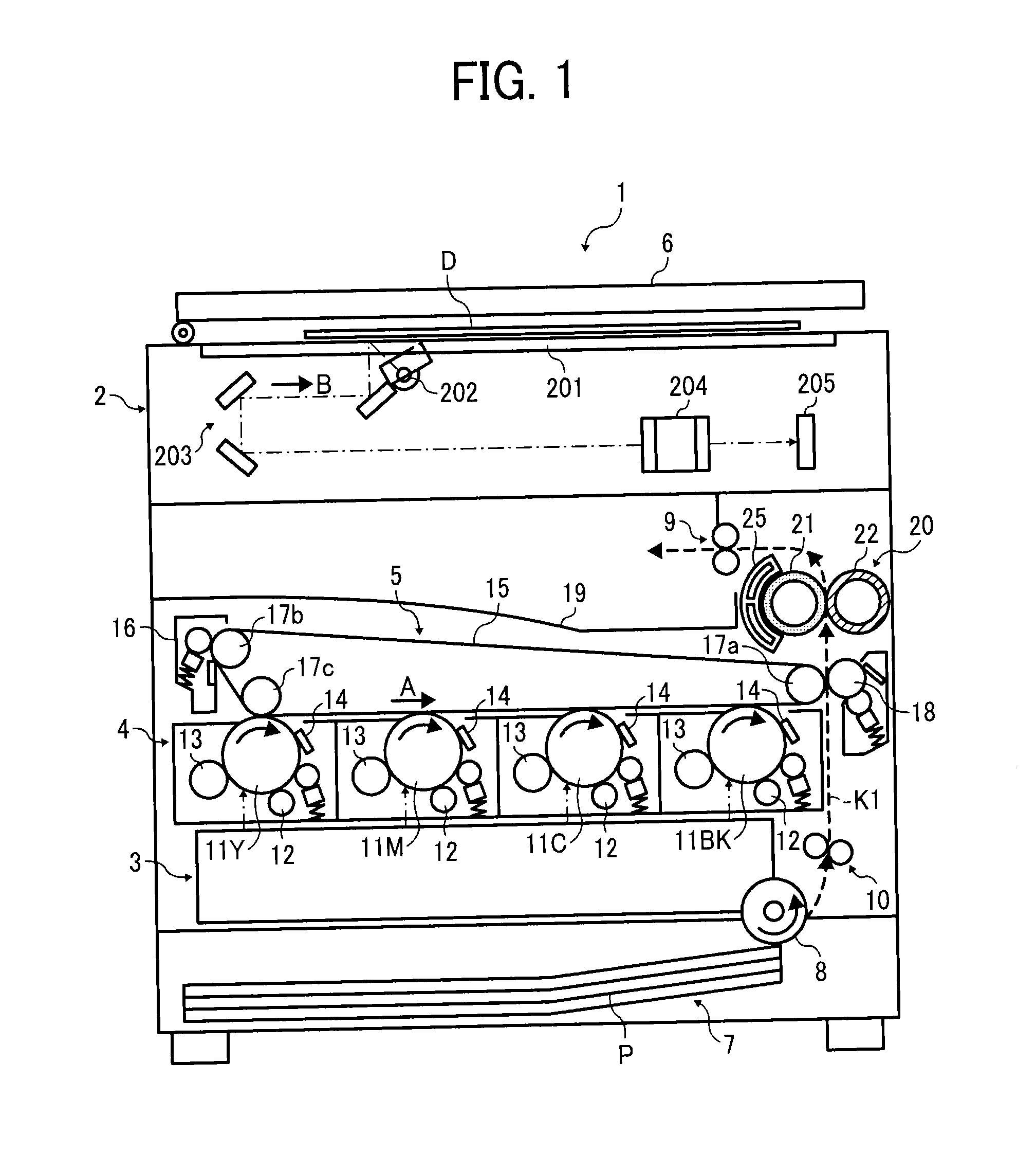
[0017]An exemplary image forming machine 1 shown in FIG. 1 is a tandem type color copier and a digital machine. It can be used as a printer by connecting to a network or PC. The image forming apparatus 1 has a scanner 2 that reads the information of a document D, an exposure unit 3 to expose a photoconductor for each color by a laser beam that is generated based on the information read by scanner, an image forming unit 4 that forms each color toner image, and a transfer unit 5 that transfer the toner image to a recording medium.

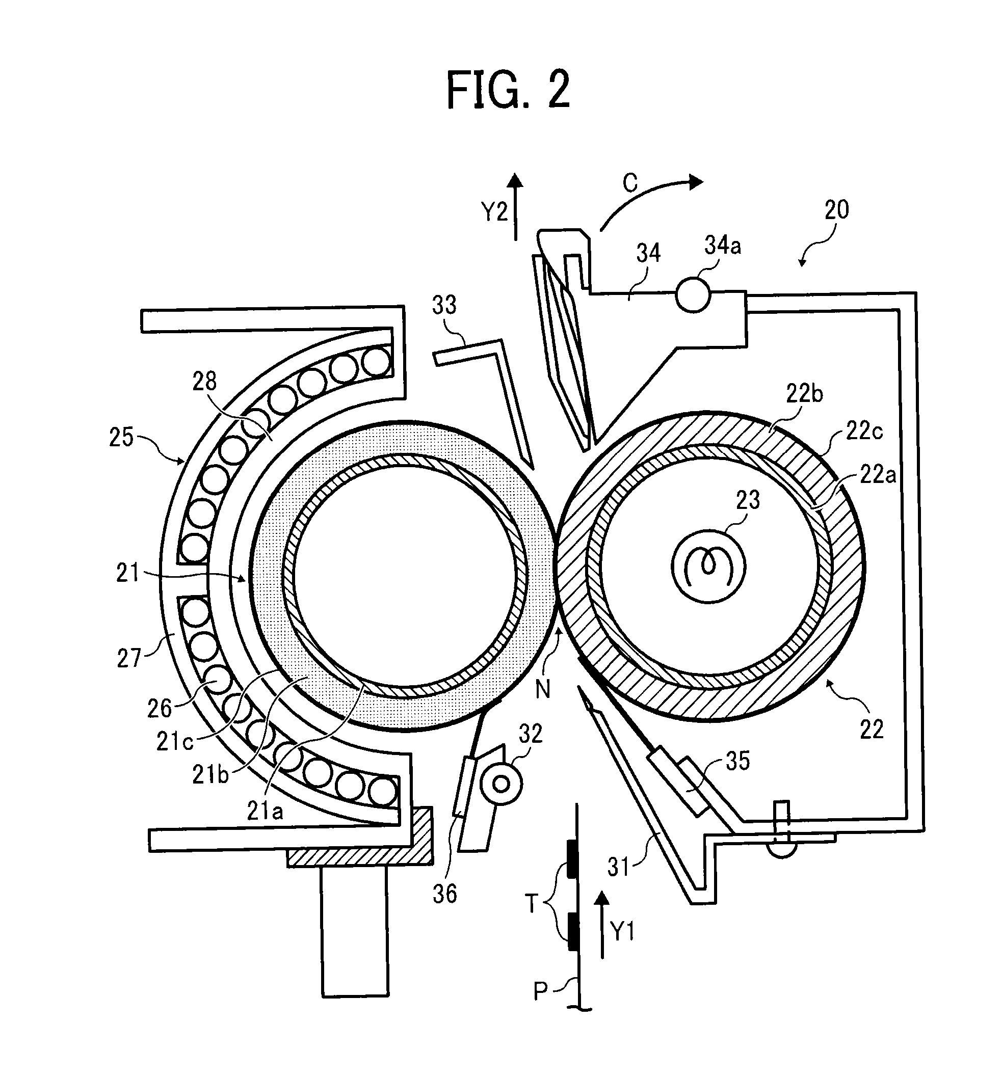
[0018]The image forming apparatus has a paper feeding unit 7 that stores paper P as a recording medium, and a fixing unit 20 with an electromagnetic induction heating unit to fix the toner image transferred by a transfer unit 5 on the paper P. The scanner 2 has a contact glass 201, an exposure lamp 202, an optical system that includes a number of mirrors 203, a lens 204, and an image pickup device 205 such as CCD color line sensors. A platen 6 presses the doc...


PUM


Abstract

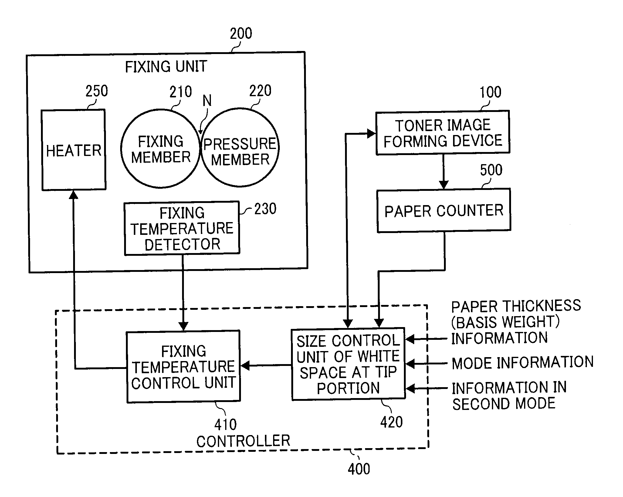
An image forming device forms a toner image on a recording medium. The recording medium goes through a fixing nip N between a fixing member and a pressure member in a fixing unit where the toner image is fixed on the recording medium. A fixing temperature detector detects the temperature of the fixing member. A fixing temperature control unit controls a heater that heats the fixing member so that the detected temperature becomes a target temperature. A size control unit of white space sets a white space at a tip of the recording medium in a direction of the recording medium movement. When a paper counter counts more than a predetermined paper count, the size control unit increases the size of the white space. The fixing temperature control unit decreases the target fixing temperature when the white space goes through the fixing nip.

Description

CROSS-REFERENCE TO RELATED APPLICATION[0001]This patent application is based on and claims priority pursuant to 35 U.S.C. §119 to Japanese Patent Application Nos. 2011-262617 filed on Nov. 30, 2011 in the Japanese Patent Office, the entire content of which is hereby incorporated by reference herein.BACKGROUND[0002]1. Technological Field[0003]The exemplary embodiments described herein relate to an image forming apparatus that has a fixing unit, such as a copier, a printer, a facsimile machine, a multi-functional digital machine, etc.[0004]2. Description of the Related Art[0005]In electrophotography, an image forming unit makes an electrostatic latent image on a photoconductor, develops it using toner, and transfers the developed toner image to a sheet of paper. A fixing unit then fixes the toner image on the paper. The fixing unit has a heated fixing member (a fixing roller, a fixing belt, etc.) and a pressure member (a pressure roller, etc.). When the toner image on the paper passes...

Claims


Application Information

Patent Timeline
Patent Type & Authority Applications(United States)
IPC IPC(8): G03G15/20
CPCG03G15/2046G03G2215/0485G03G15/36
Inventor YUASA, SHUUTAROHUCHITANI, TAKESHIHASE, TAKAMASAIKEBUCHI, YUTAKAYOSHINAGA, HIROSHISESHITA, TAKUYA
Owner RICOH KK
Learn More