
Leadless system for deep brain stimulation using time reversal acoustics

Inactive Publication Date: 2013-05-23
ARTANN LAB
View PDF8 Cites 58 Cited by
  • Summary
  • Abstract
  • Description
  • Claims
  • Application Information

AI Technical Summary

Benefits of technology

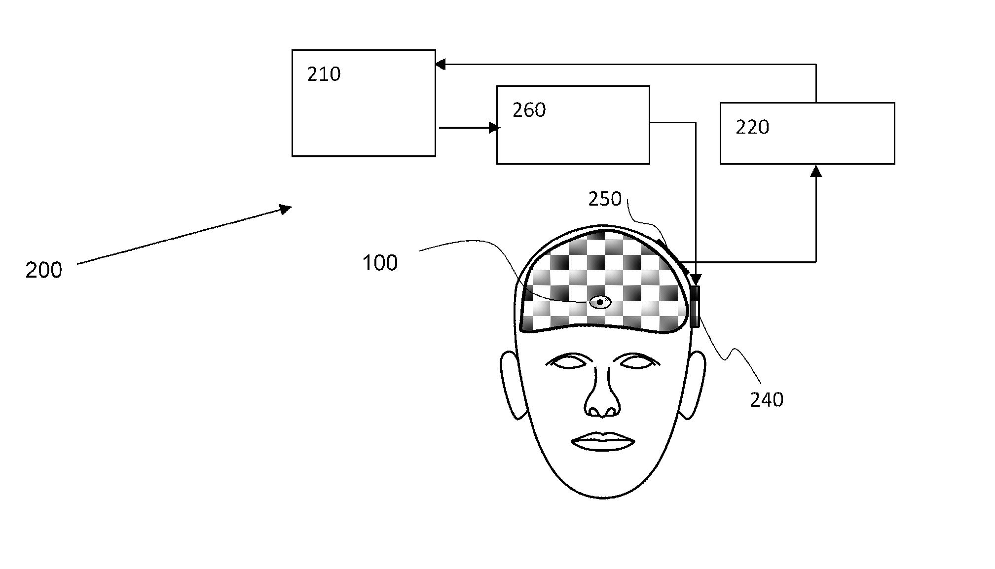
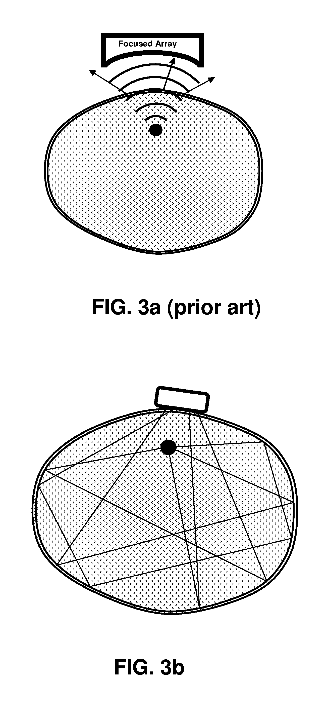
The present invention provides a novel leadless neurostimulation system capable of focused energy delivery at the desired part of the brain. The system includes an implantable stimulator and external elements collaborating together in transmitting the required energy and control signals to the desired stimulation site in the brain. The system uses principles of time-reversal acoustics and a skull as a reverberation chamber to focus ultrasound energy onto the location of the implanted stimulator. The process involves sending an initial unfocused acoustic signal, receiving the acoustic waveform after reverberation in the skull and generating a radiofrequency feedback signal, time-reversing the signal, and sending a second acoustic signal to the stimulator to carry sufficient energy to operate it for DBS purposes. Focusing of acoustic energy may be repeated from time to time to ensure proper energy delivery only to the site of the stimulator and not to surrounding tissues. Overall, this system allows for efficient and targeted deep brain stimulation.

Problems solved by technology

Tremor may not be eliminated, and may continue to cause some impairment.
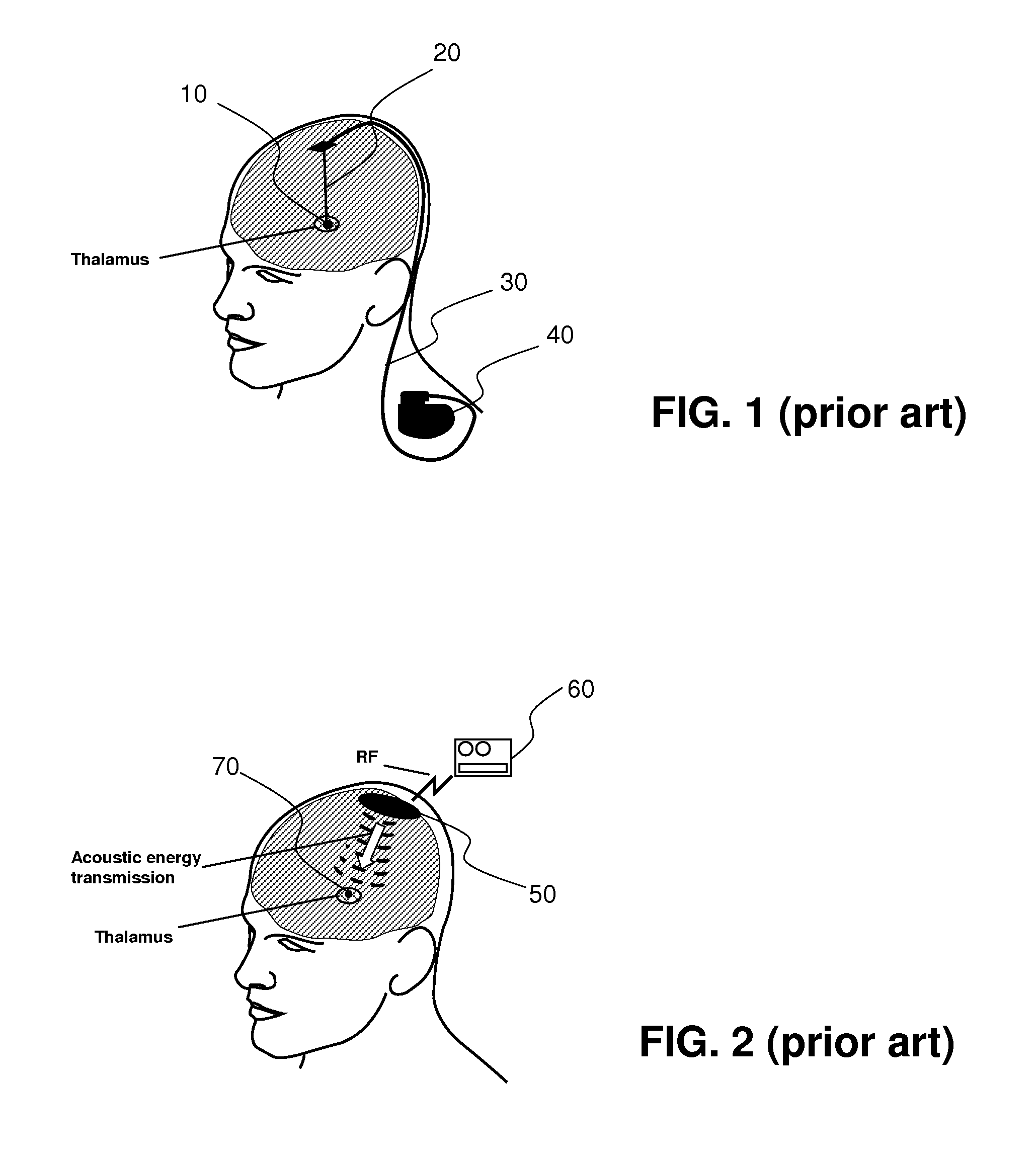
There have been reported attempts to eliminate implant's leads, a major source of complications and reliability issue.
For example, self-contained implantable microstimulators and remotely-powered microstimulators have been described; however, each approach suffers from some significant limitation.
A self-contained microstimulator must incorporate a battery or some other power supply; this imposes constraints on size, device lifetime, available stimulation energy, or all three.
Often, DBS devices contain rechargeable batteries due to high use or high energy requirements of the therapeutic stimulation.
RF energy transmission, unless the transmitting and receiving antennae are placed in close proximity, suffers from inefficiency and restricted safe power transfer capabilities, limiting its usefulness in applications where stimulation must be accomplished at any significant depth (>1-2 cm) within the body, in particular where it is desired to permanently implant both the transmitter and receiver-stimulator.
In such arrangement it is difficult to deliver sufficient levels of acoustic energy to the stimulator without negatively affecting (overheating) surrounding tissues.
Poor energy efficiency of currently known systems is a major obstacle to broad use of leadless implantable device.
The efficiency of conventional methods of ultrasound focusing is often limited in biological tissues by spatial heterogeneities in sound velocity and by reflective surfaces and boundaries.
This challenge is especially great for focusing through the skull bone, which induces severe refractions and scattering of the ultrasonic beam.
There are many methods of improving ultrasonic focusing in complex media based on phase and amplitude corrections in the focusing system, but they are often complicated, and, in some cases, do not provide the necessary improvement.
An important issue in the TRA method of focusing acoustic energy is related to obtaining initial signal from the target area.
The need to have a beacon in the target region limits the applications of TRA focusing methods.

Method used


Image

  • Leadless system for deep brain stimulation using time reversal acoustics
  • Leadless system for deep brain stimulation using time reversal acoustics
  • Leadless system for deep brain stimulation using time reversal acoustics

Examples


Embodiment Construction

[0041]The following description sets forth various examples along with specific details to provide a thorough understanding of claimed subject matter. It will be understood by those skilled in the art, however, that claimed subject matter may be practiced without one or more of the specific details disclosed herein. Further, in some circumstances, well-known methods, procedures, systems, components and / or circuits have not been described in detail in order to avoid unnecessarily obscuring claimed subject matter. In the following detailed description, reference is made to the accompanying drawings, which form a part hereof. In the drawings, similar symbols typically identify similar components, unless context dictates otherwise. The illustrative embodiments described in the detailed description, drawings, and claims are not meant to be limiting. Other embodiments may be utilized, and other changes may be made, without departing from the spirit or scope of the subject matter presented...


PUM


Abstract

A leadless Deep Brain Stimulation system includes an implantable stimulator configured to convert incoming acoustic energy into an electric stimulation signal. The acoustic energy is provided by one or more external transmitters acoustically coupled to a head of the subject. To focus ultrasound energy onto the location of the stimulator, a wireless beacon (including a piezoelectric receiving transducer and an RF emitting antenna) is incorporated with the stimulator for providing an electromagnetic feedback signal to the external controller. The external controller is configured to send an initial unfocused acoustic signal towards the stimulator and receive the electromagnetic radiofrequency feedback signal generated by the receiving piezotransducer when affected by the acoustic signal after reverberation in the skull. This signal is then time-reversed and used to send a second signal towards the stimulator. This signal is inherently focused on the site of the stimulator and is configured to carry sufficient energy to operate the stimulator for DBS purposes.

Description

CROSS-REFERENCE DATA[0001]This patent application is a continuation-in-part of a co-pending U.S. patent application Ser. No. 13 / 448,530 filed 17 Apr. 2012 entitled “SYSTEMS FOR REMOTE GENERATION OF ELECTRICAL SIGNAL IN TISSUE BASED ON TIME-REVERSAL ACOUSTICS”; which in turn is a continuation-in-part of a co-pending U.S. patent application Ser. No. 13 / 028,301 filed 16 Feb. 2011 entitled “ULTRASOUND DIAGNOSTIC AND THERAPEUTIC DEVICES”; which is in turn a continuation-in-part of a U.S. patent application Ser. No. 12 / 766,383 filed 23 Apr. 2010 entitled “Ultrasound-assisted drug-delivery method and system based on time reversal acoustics”, now U.S. Pat. No. 7,985,184; which in turn is a continuation-in-part of U.S. patent application Ser. No. 11 / 223,259 filed 10 Sep. 2005 entitled “Wireless beacon for time-reversal acoustics, method of use and instrument containing thereof”, now U.S. Pat. No. 7,713,200. All of the above mentioned patent documents are incorporated herein by reference in t...

Claims


Application Information

Patent Timeline
IPC IPC(8): A61N1/36
CPCA61N1/3606A61N1/37252A61B8/0841A61B8/12A61B5/061A61B19/5244A61B19/54A61M37/0092A61B2017/00411A61B2017/3413A61B2019/5263A61B2019/5278A61B2019/5429A61N1/3756A61N1/36064A61N1/36067A61N1/36071A61N1/36082A61N1/37205A61N1/37217A61N1/3787A61B34/20A61B90/39A61B2034/2063A61B2090/3782A61B2090/3929
Inventor SARVAZYAN, ARMEN P.
Owner ARTANN LAB
Learn More