Battery pack
a battery pack and stacked technology, applied in the manufacture of final products, cell components, electrochemical generators, etc., can solve the problems of insufficient structure of the battery pack disclosed in the patent document to meet the recent demand and strict requirements, and achieve the effect of shortening the distance between the control device and the battery cell, reducing size, and suppressing the height direction (or the stacked direction) of the battery pack
- Summary
- Abstract
- Description
- Claims
- Application Information
AI Technical Summary
Benefits of technology
Problems solved by technology
Method used
Image


Examples
first exemplary embodiment
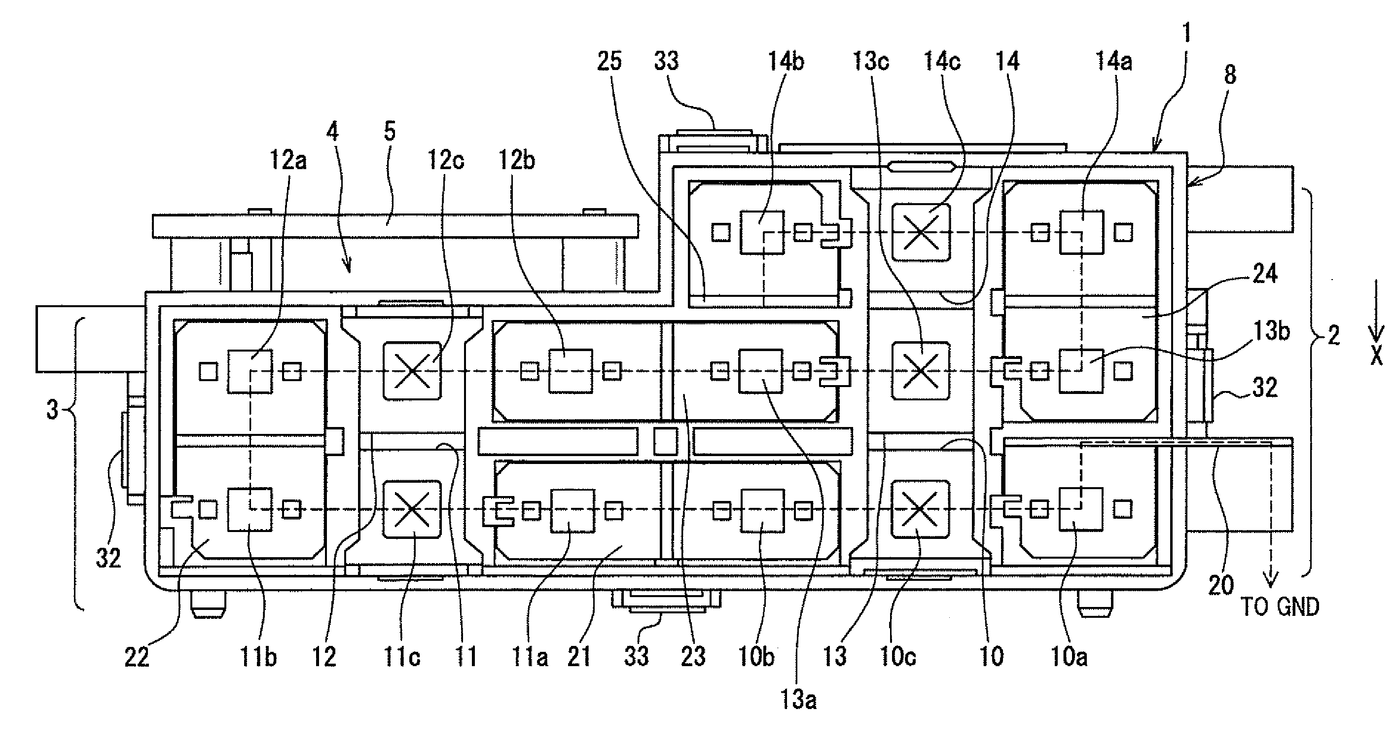
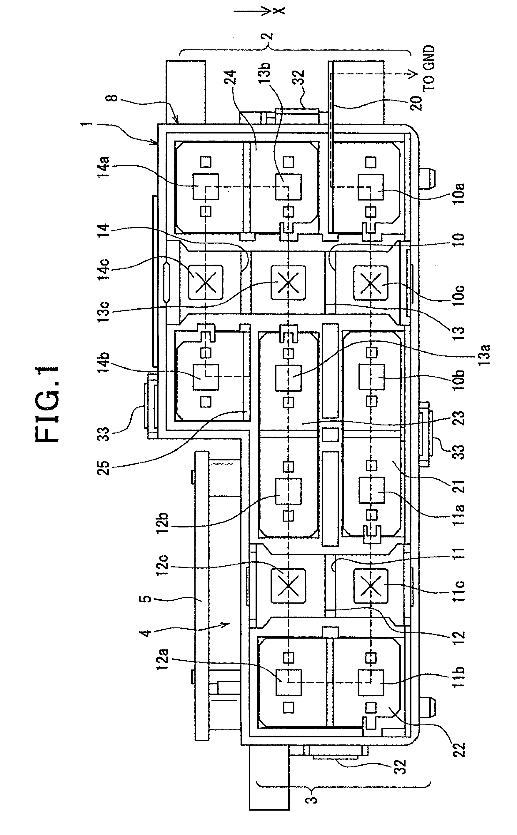
[0029]A description will be given of a battery pack 1 (or a battery module) according to the first exemplary embodiment with reference to FIG. 1 to FIG. 8.
[0030]FIG. 1 is a front view showing the battery pack 1 having five battery cells 10, 11, 12, 13 and 14 and a control board 5 according to the first exemplary embodiment of the present invention.
[0031]As shown in FIG. 1, the battery pack 1 has five battery cells 10, 11, 12, 13 and 14, The concept of the present invention does not limit the number of the battery cells. It is therefore possible for a battery pack 1 to have a plurality of battery cells, Each of the battery cells 10, 11, 12, 13 and 14 in the battery pack 1 has an exterior case 10e, 11e, 12e, 13e or 14e and a positive electrode terminal and a negative electrode terminal. The exterior case 10e, 11e, 12e, 13e, 14e of each battery cell is made of aluminum.
[0032]In each of the battery cells 10, 11, 12, 13 and 14, the electrode terminals are composed of a positive electrode...
second exemplary embodiment
[0104]A description will be given of a battery pack 1A according to a second stacked group exemplary embodiment with reference to FIG. 9 and FIG. 10.
[0105]FIG. 9 is a perspective view showing the arrangement of the battery pack 1A having the discharge duct 6 according to a second exemplary embodiment of the present invention. FIG. 10 is a plan view showing a structure in which the cover case 60 is removed from the battery pack 1A according to the second exemplary embodiment of the present invention;
[0106]The same components between the second exemplary embodiment and the first exemplary embodiment will be referred with the same reference characters and numbers. The explanation of the same components between the second exemplary embodiment and the first exemplary embodiment is omitted here for brevity.
[0107]As shown in FIG. 9 and FIG. 10, the battery pack 1A has a bus bar 25A which is electrically connected to the control board 5. On the other hand, the bus bar 25 used in the battery...
third exemplary embodiment
[0110]A description will be given of a battery pack 1B according to a third exemplary embodiment with reference to FIG. 11 and FIG. 12.
[0111]FIG. 11 is a perspective view showing an arrangement of the battery pack 1B having a discharge duct 6A according to the third exemplary embodiment of the present invention. FIG. 12 is a plan view showing a structure in which the cover case 6 is removed from the battery pack 1B according to the third exemplary embodiment of the present invention.
[0112]The same components between the third exemplary embodiment and the first exemplary embodiment will be referred with the same reference characters and numbers. The explanation of the same components between the third exemplary embodiment and the first exemplary embodiment is omitted here for brevity.
[0113]The battery pack 1B according to the third exemplary embodiment shown in FIG. 11 and FIG. 12 has a control board 70 on which the control board 5 and the power board 50 are mounted.
[0114]As shown in...
PUM
 Abstract
Description
Claims
Application Information
 - Generate Ideas
- Intellectual Property
- Life Sciences
- Materials
- Tech Scout
- Unparalleled Data Quality
- Higher Quality Content
- 60% Fewer Hallucinations
Browse by: Latest US Patents, China's latest patents, Technical Efficacy Thesaurus, Application Domain, Technology Topic, Popular Technical Reports.
© 2025 PatSnap. All rights reserved.Legal|Privacy policy|Modern Slavery Act Transparency Statement|Sitemap|About US| Contact US: help@patsnap.com