
Concave receiver for stirling dish and manufacturing method therefor

a technology of solar collector and receiver, which is applied in the direction of machines/engines, other domestic objects, light and heating apparatus, etc., can solve the problems of premature failure of the receiver, thermal fatigue of the components, and thermal fatigue caused by the fatigu

Inactive Publication Date: 2013-05-23
ABENGOA SOLAR NEW TECH SA
View PDF6 Cites 0 Cited by
  • Summary
  • Abstract
  • Description
  • Claims
  • Application Information

AI Technical Summary

Benefits of technology

The patent text describes a new design for concentrating solar receivers that improves their performance and increases the amount of sunlight that can be captured. The design includes tubes that form the surface area where the concentrated solar light falls, which are placed close together to maximize the amount of sunlight that can be absorbed. The receiver model and its manufacturing process comply with these design constraints, resulting in improved thermo-mechanical behavior compared to existing receivers.

Problems solved by technology

The high temperature is the most important factor which, together with cycle operation, gives rise to the thermal fatigue of the components.
Thermal fatigue is caused by the temperature cycles, from room temperature to operation temperature, both in the starts and stops and during the moments of cloudiness.
This type of cycle can cause premature failure of the receiver.

Method used


Image

  • Concave receiver for stirling dish and manufacturing method therefor
  • Concave receiver for stirling dish and manufacturing method therefor
  • Concave receiver for stirling dish and manufacturing method therefor

Examples


Embodiment Construction

[0045]The invention consists of a new receiver for Stirling dish that complies with the requirements defined previously.

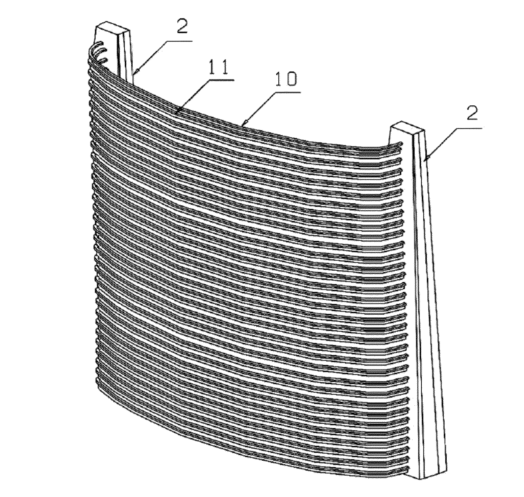
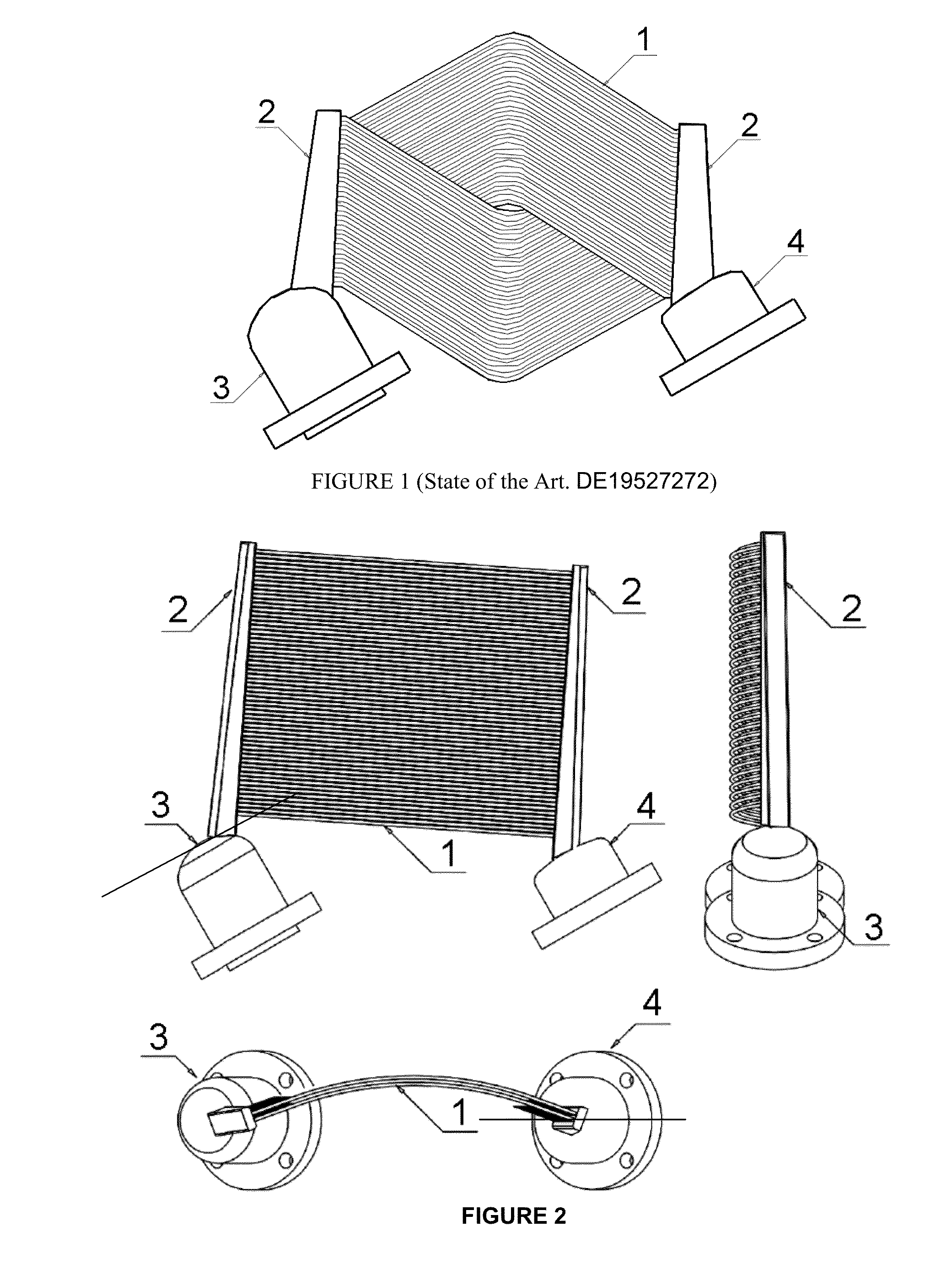
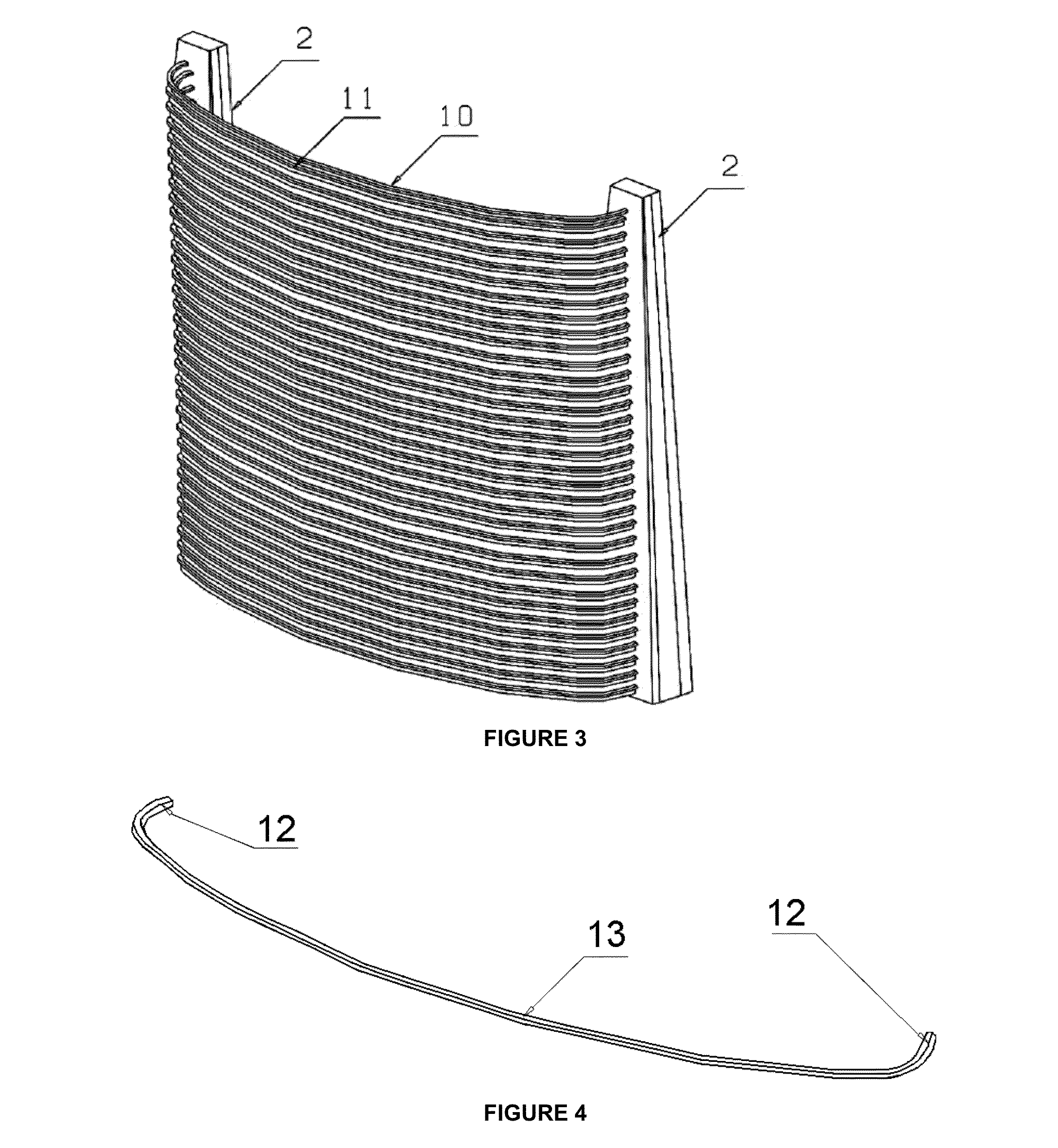
[0046]The designed receiver comprises the following components: tubes, collectors, tanks and cupolas.[0047]Tubes: The tubes form the surface where the concentrated solar light beam falls. They are arranged very close to each other so that the surface has few gaps and the striking radiation can be maximized.[0048]Collectors: The collectors are the areas where the tubes are welded such that the flow that runs through the tubes is communicated with the tanks.[0049]Tanks: The tanks are the internal areas of the collectors; from here the working gas is distributed to each of the tubes.[0050]Cupolas: There are two cupolas: the one for housing the regenerator (or heat exchanger capable of absorbing heat from the working gas, storing it and transferring it to the same to close the cycle and it is, of the exchangers that the engine contains, the one that handles a greater v...


PUM

PropertyMeasurementUnit
circumferenceaaaaaaaaaa
angleaaaaaaaaaa
circumferenceaaaaaaaaaa

Abstract

Concave receiver for a Stirling dish the main components of which are tubes (which form the surface on which the concentrated solar light beam falls), collectors (welded to the tubes and place the fluid that runs through the tubes in communication with the tanks), tanks (the internal areas of the collectors from which the working gas is distributed to each of the tubes) and cupolas (of which there are two types, that for housing the regenerator and the expansion cupola which is the area where the working gas is at a higher temperature) comprising a series of tubes (10, 11) extending from one collector (2), perpendicular thereto, to the other (2), also perpendicular thereto, and having a straight part (12) running from the inside of each collector (2) to the point where the tube starts to curve and a central part (13) in the shape of an arc of a circumference.

Description

TECHNICAL FIELD OF THE INVENTION[0001]The invention is framed within the technology of solar collectors and more specifically it is focused on the design of solar receivers for Stirling dish.BACKGROUND OF THE INVENTION[0002]The Stirling dish systems are electricity generation units that use solar radiation as a source of energy. The capacity of a single unit is between 3 and 50 kWe.[0003]The Stirling dish systems transform with high efficiency the concentrated solar radiation into electrical energy. The essential components of the system are:[0004]Parabolic solar concentrator.[0005]Solar heat exchanger (solar receiver).[0006]Stirling Engine with electric generator.[0007]Tracking system.[0008]The mode of operation of a Stirling dish system is the following: the concentrator reflects the solar radiation to the receiver which is located at the focal point of the concentrator. The solar radiation is absorbed in the receiver and this heats the gas (helium or hydrogen) of the Stirling eng...

Claims


Application Information

Patent Timeline
Patent Type & Authority Applications(United States)
IPC IPC(8): F24J2/24B21D53/06F24S10/70F24S20/20
CPCF24J2/07Y02E10/41Y02E10/46F02G2254/30Y10T29/49355F24J2/24F03G6/068F24J2/248Y02E10/44B21D53/06F24S20/20F24S10/748F24S10/70Y02E10/40
Inventor NUNEZ BOOTELLO, JUAN PABLOSOSA NARANJO, CRISTINAMONNE BAILO, CARLOS MIGUELMORENO GOMEZ, FRANCISOMUNOZ RODRIGUEZ, MARIANO
Owner ABENGOA SOLAR NEW TECH SA
Learn More