
Method for regulating the relative position of an analyte in relation to a light beam

a technology of relative position and light beam, which is applied in the direction of analysis by material excitation, instruments, measurement devices, etc., can solve the problem of imposing a relatively long alignment tim

Active Publication Date: 2017-08-22
COMMISSARIAT A LENERGIE ATOMIQUE ET AUX ENERGIES ALTERNATIVES
View PDF5 Cites 0 Cited by
  • Summary
  • Abstract
  • Description
  • Claims
  • Application Information

AI Technical Summary

Benefits of technology

The patent describes a method for optimizing the measurement of light emitted by a sample by adjusting the position of the sample in relation to the light beam. The technical effect is an increase in the amount of light emitted from the sample, resulting in more accurate and reliable measurements.

Problems solved by technology

This is delicate when the dimensions of the analyte are small, for example of the order of one micrometer.
But, this system imposes a relatively long alignment time.

Method used


Image

  • Method for regulating the relative position of an analyte in relation to a light beam
  • Method for regulating the relative position of an analyte in relation to a light beam
  • Method for regulating the relative position of an analyte in relation to a light beam

Examples


second embodiment

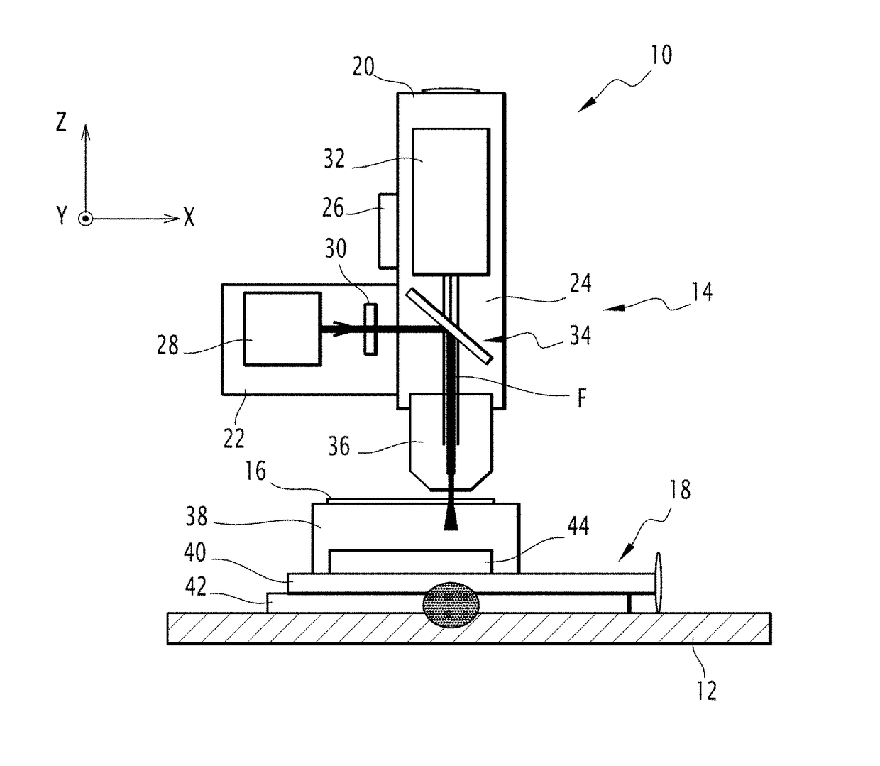
[0166]the optical system is also shown in FIG. 24.

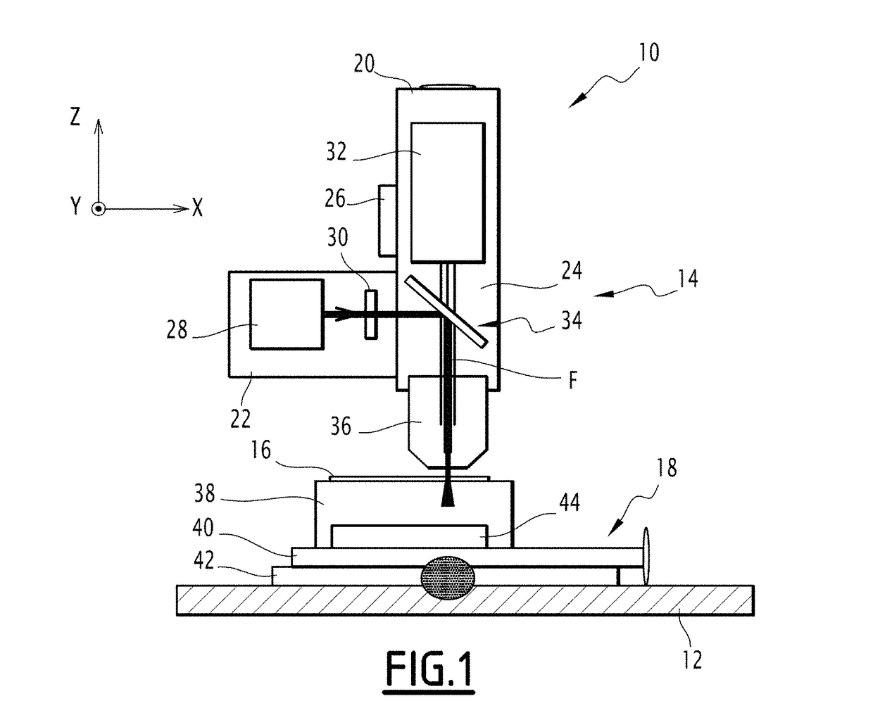
[0167]The optical system 10 includes the same elements as the optical system of FIG. 1.

[0168]The optical system 10 also includes a mirror 100 positioned between the analysis device 32 and the splitter plate 34.

[0169]The mirror 100 is a planar mirror.

[0170]The mirror 100 is movable between a first position in which it reflects the beam transmitted by the splitter plate 34 and a second position in which it does not interact with the transmitted beam.

[0171]The optical system 10 also includes a fluorescence filter 102 able to filter a light beam.

[0172]The filter 102 is positioned so as to filter a beam reflected by the mirror 100 and the splitter plate 34 when the mirror 100 is in the first position.

[0173]The optical system 10 also includes an imaging device with a lens 104.

[0174]According to the example of FIG. 24, the imaging device with the lens 104 comprises magnification optics 106 and a camera 108.

[0175]The magnification optics 106...

first embodiment

[0180]This optical system 10 also allows the application of the alignment method proposed for the optical system 10.

[0181]Consequently, in the proposed embodiment, it is possible to perform a single alignment in order to conduct two successive different analyses on the sample 16.

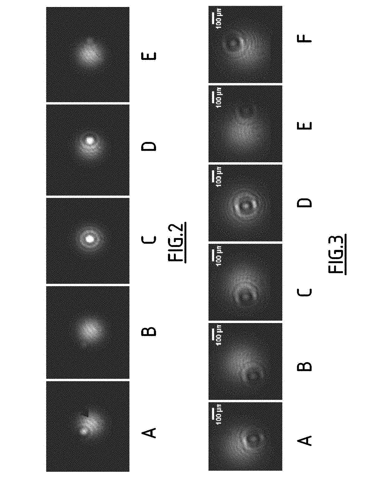
[0182]Further, although the different embodiments have been presented with reference to an imaging device 38 without any lenses, the method may also be applied with an imaging device 38 with lenses provided that the latter allows observations in Fourier space. Indeed, according to the invention, alignment of an analyte is proposed by using properties observed in Fourier space and not in direct space as this is the case in the state of the art. The regulation method which results from this is faster to apply than the regulation methods of the state of the art.


PUM


Abstract

A method for regulating the relative position of an analyte of a sample (16) in relation to a light beam (F) includes the illumination of the analyte of the sample (16) with the light beam (F), capturing by an imaging device (38) a transmission image of the beams scattered by the analyte of the sample (16) in order to establish a diffraction pattern, and modifying the relative position of the analyte of the sample (16) in relation to the light beam (F) according to at least one property of the diffraction pattern.

Description

BACKGROUND OF THE INVENTION[0001]The present invention relates to a method for regulating the relative position of an analyte of a sample in relation to a light beam. The present invention also relates to a method for analyzing an analyte of a sample by means of a light beam. The present invention also relates to the associated sample holder and optical system.DESCRIPTION OF THE RELATED ART[0002]In the field of spectrometric analysis, an analysis device comprising an optical probe is used. The optical probe allows excitation of an analyte, which allows a signal to be collected stemming from the analyte as a response to the excitation of the probe. The quality of the signal and therefore of the analysis implies alignment of the optical probe on the analyte as accurately as possible. This is delicate when the dimensions of the analyte are small, for example of the order of one micrometer.[0003]In order to produce the alignment, a system including an analysis device with an optical pro...

Claims


Application Information

Patent Timeline
IPC IPC(8): G01B11/02G01N21/65G01N21/01G01N21/13G01N33/00G01N21/00G03H1/04
CPCG01N21/65G01N21/01G01N21/13G03H1/0443G01N2021/135G03H2001/045G03H2001/0447
Inventor STROLA, SAMYALLIER, CEDRICDUPOY, MATHIEUSCHULTZ, EMMANUELLE
Owner COMMISSARIAT A LENERGIE ATOMIQUE ET AUX ENERGIES ALTERNATIVES
Learn More