Process and Apparatus for Reducing EMI in the RF Subsystem of a Wireless Communication System

a wireless communication system and subsystem technology, applied in the field of wireless communication, can solve the problems of increasing the design and manufacturing costs of the transceiver, reducing the service life of the rf receiver, and not allowing to avoid desensitization of the receiver, so as to facilitate the cellular integration

Active Publication Date: 2013-05-16
TELEFON AB LM ERICSSON (PUBL)
View PDF6 Cites 6 Cited by
  • Summary
  • Abstract
  • Description
  • Claims
  • Application Information

AI Technical Summary

Benefits of technology

This patent aims to provide a new method for better integrating digital and RF components in a mobile phone. The invention helps avoid desensitizing the RF receiver while still using the phone's RF subsystem. The patent also introduces a technique for minimizing the impact of harmonic noise in RF receivers, which can be a source of desensitization. Overall, the invention improves wireless communication in mobile phones.

Problems solved by technology

However, despite the significant cost saving resulting from the use of a single RF-BB-PMU chip, some significant EMI problems need to be considered in order to prevent the RF receiver as well as the RF transmitter chain from being polluted by digital BB and external memory bus noise, as well as associated clock spurs, and their multiple harmonics.
All those techniques clearly tend to increase the design and manufacturing costs of the transceiver IC.
In some situations, those techniques do not allow to avoid desensitization of the receiver in some circumstances.
In particular, it has been shown that multiple integer harmonics of the reference clock used to transfer data over the external memory interface desensitize degrade an RF receiver.

Method used


Image

  • Process and Apparatus for Reducing EMI in the RF Subsystem of a Wireless Communication System
  • Process and Apparatus for Reducing EMI in the RF Subsystem of a Wireless Communication System
  • Process and Apparatus for Reducing EMI in the RF Subsystem of a Wireless Communication System

Examples


Embodiment Construction

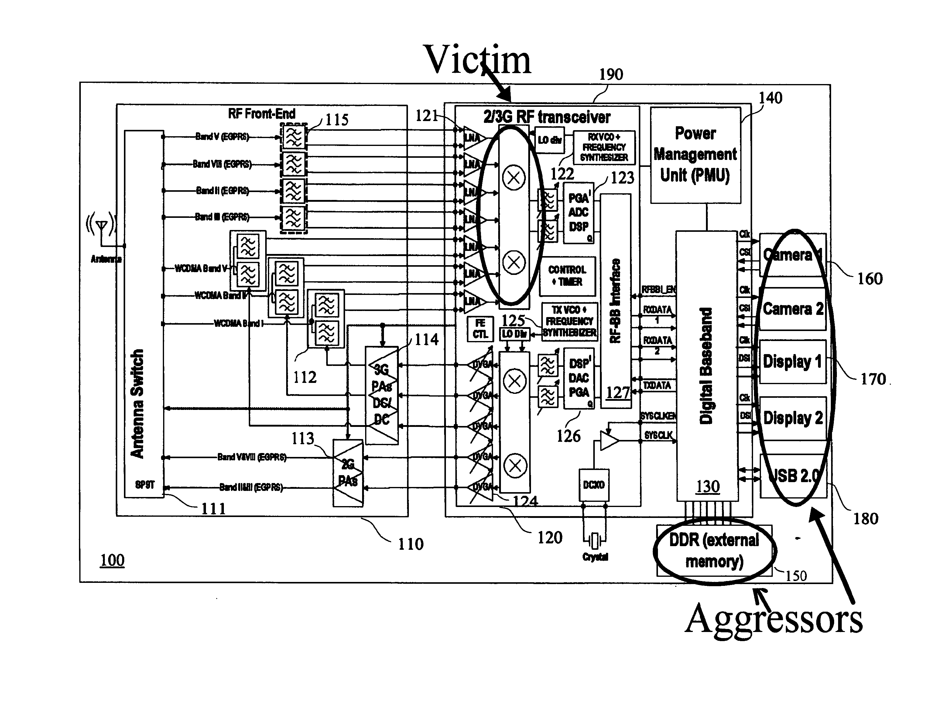
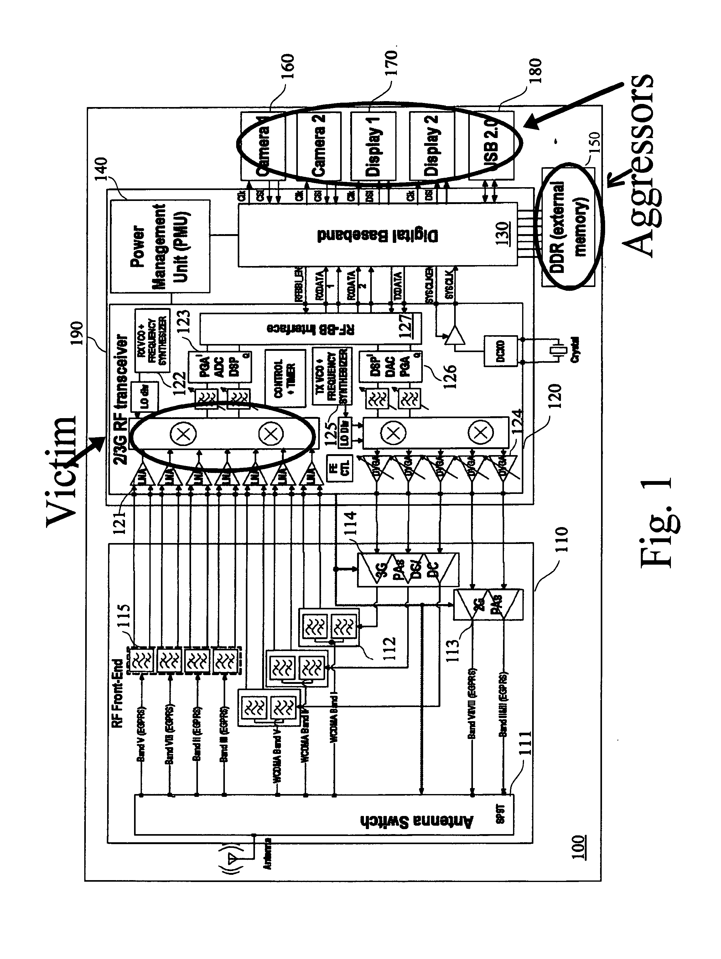
[0054]It will now be described how one can improve the integration of digital baseband systems and circuits with one or more RF subsystem. Clearly, the method and system being described hereinafter are particularly suitable for the purpose of designing an new mobile phone fitted with multimedia and enhanced functionalities, such as Global Positioning System (GPS), Bluetooth, wireless Ian, 2G and 3G, a high resolution camera and display(s) a TV out capability etc. . .

[0055]Clearly, the clocking architecture which will be described is suitable for allowing combination of wide number of features and functions such as mentioned above, but can also be used for a limited subset of functionalities.

[0056]Furthermore, it should be clear that the embodiments which will be described hereinafter should not be restricted to the telecommunication standards, nor to the frequency bands nor to the combination of bands which are shown in the illustrative example of FIG. 1. The technique described bel...


PUM


Abstract

A method for dynamically clocking one component located into a Wireless telecommunication apparatus comprising a RF transceiver subject to desensizitation by said component EMI, characterized in that it involves the steps of performing an adaptive control on the clock rate of said component so as to locate a wideband noise PSD null just to the left or to the right, in the frequency domain, of the RF transceiver wanted carrier frequency (fw) Particularly, the control is performed by means of the control of programmable frequency dividers, and under the control of a general control unit (UCM) for the purpose of performing a contextual analysis of the current mode of operation of said wireless telecommunications and, in response to said contextual analysis, for determining the fine tuning of the clock rate to be applied to said component.

Description

TECHNICAL FIELD [0001]The invention relates to the field of wireless communications and more particularly to a process and apparatus for reducing EMI in the RF subsystem of a wireless communication system .BACKGROUND ART[0002]Until recently, mobile wireless equipment used separate Integrated Circuits (ICs) for the Radio Frequency (RF) transceiver, the baseband (BB) processor and the Power Management Unit (PMU). In the context of the permanent perpetual quest for cost reduction, the approach taken by most IC vendors is that of a single chip, made up of either a single RF CMOS die, or multiple separate dies, which integrates into a single package all three previously listed ICs, namely, RF, BB and PMU into a single package.[0003]FIG. 1 shows a typical general architecture of a multiple-band 2G / 3G phone 100 consisting of a quad band 2.75G (EGPRS), triple band 3G (HSPA+) with 3G receive diversity, comprising one single die 190, of a RF Front End circuit 110, a 2G / 3G RF transceiver 120, ...

Claims


Application Information

Patent Timeline
IPC IPC(8): H04B15/02
CPCH04B15/04H04B15/02
Inventor SITTLER, FRANCOISBRUNEL, DOMINIQUENOEL, LAURENT
Owner TELEFON AB LM ERICSSON (PUBL)
Why Eureka
Try Eureka