
Refrigerant compressor

a compressor and refrigerant technology, applied in the direction of pump control, non-positive displacement fluid engine, pump components, etc., can solve the problems of less cooling effect provided by oil, oil is not fed to the small end hole b>8/b> sufficiently, wear out, etc., to achieve high reliability and suppress wear out of sliding surface

Active Publication Date: 2013-05-16
PANASONIC APPLIANCES REFRIGERATION DEVICES SINGAPORE
View PDF4 Cites 2 Cited by
  • Summary
  • Abstract
  • Description
  • Claims
  • Application Information

AI Technical Summary

Benefits of technology

The present invention addresses the issue of wear out of the sliding surface of piston pin and connecting rod in refrigerant compressors. The invention provides a configuration that allows sufficient lubricating oil to be fed to the sliding surfaces through communication between two grooves on the piston pin and connecting rod. This helps to prevent wear and tear, ensuring high reliability of the compressor.

Problems solved by technology

In the refrigerant compressor, the piston pin and a hole portion of the connecting rod are applied with a great surface pressure (load) during the compression action and thereby wear out.
Therefore, there is a possibility that the oil is not fed to the small end hole 8 sufficiently.
When the oil is not fed to the small end hole 8 sufficiently, a cooling effect provided by the oil is lessened, and insufficient lubrication due to the insufficient oil feeding and a temperature increase in the sliding portion may occur.

Method used


Image

  • Refrigerant compressor
  • Refrigerant compressor
  • Refrigerant compressor

Examples


embodiment 1

[Configuration of Refrigerant Compressor]

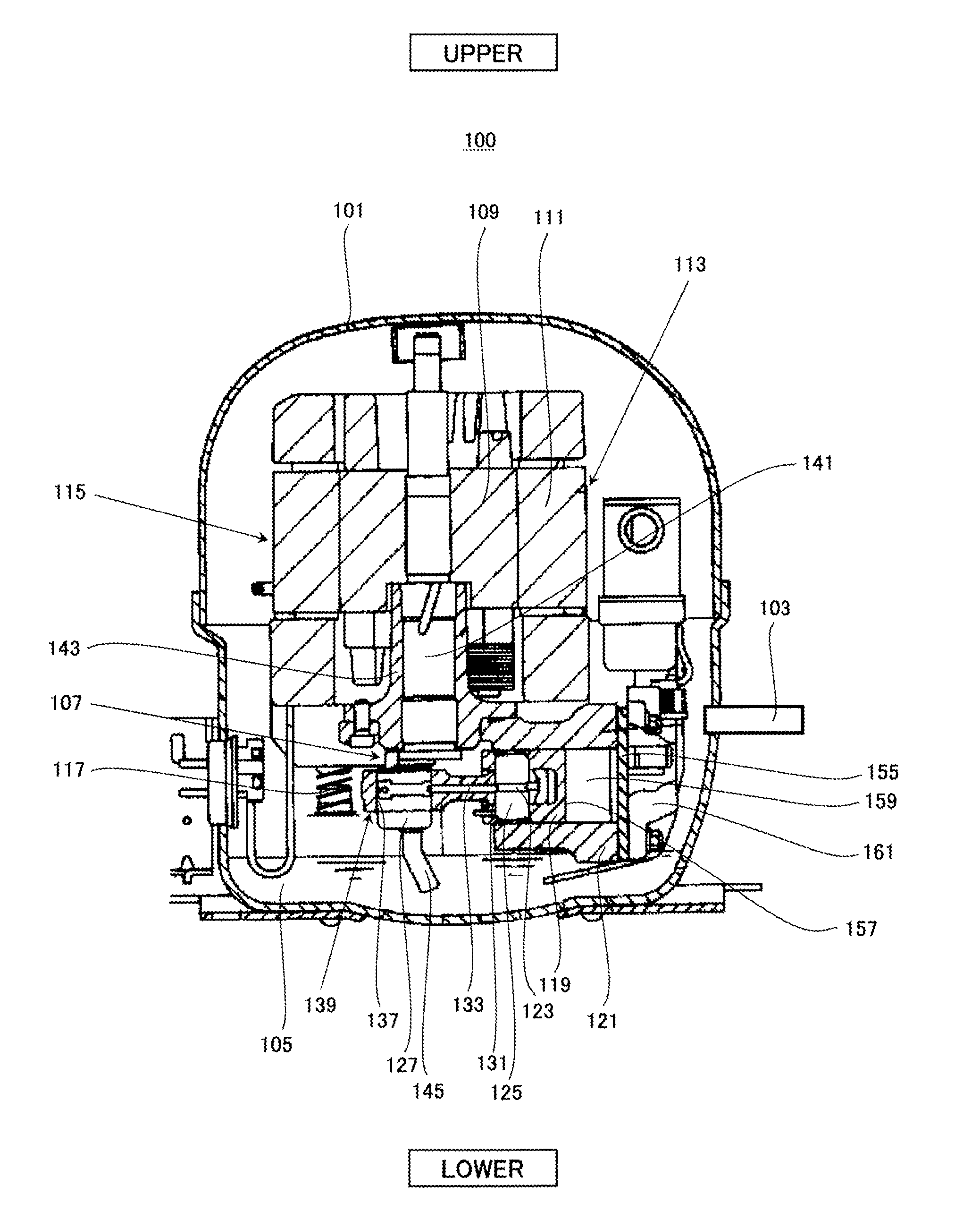
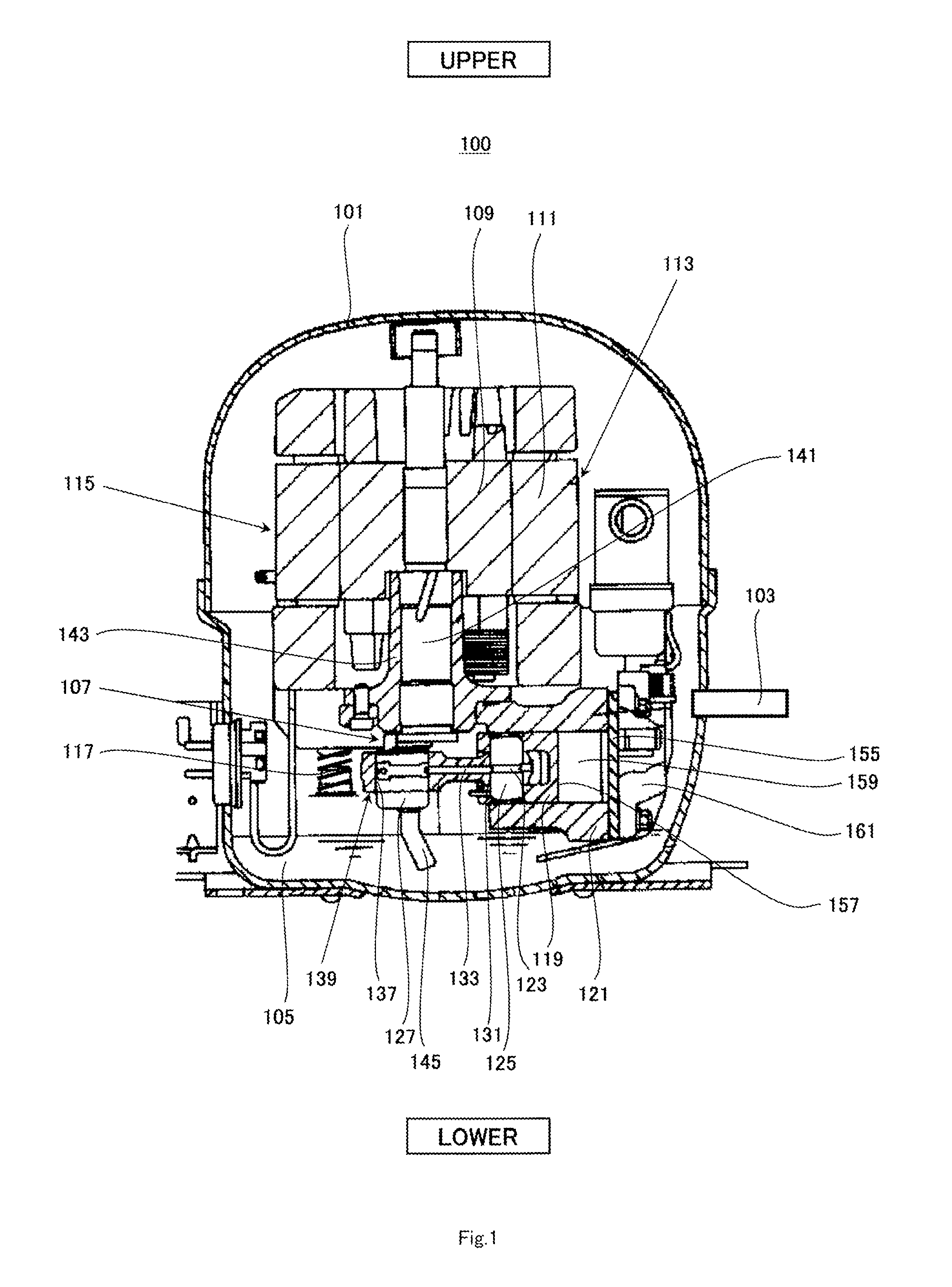
[0027]FIG. 1 is a cross-sectional view of a side surface of a refrigerant compressor according to Embodiment 1. In FIG. 1, upper and lower sides of the refrigerant compressor are depicted as upper and lower sides of FIG. 1.

[0028]Referring to FIG. 1, a refrigerant compressor 100 of Embodiment 1 includes a sealed container 101. The sealed container 101 is provided with a suction pipe 103 penetrating a wall portion of the sealed container 101. A refrigerant gas (not shown) supplied from a refrigeration cycle (not shown) flows through the suction pipe 103 and is fed to inside of the sealed container 101.

[0029]Lubricating oil 105 is reserved in a bottom portion of the sealed container 101. Inside of the sealed container 101, a compressor body 115 including a compression element 107 for suctioning and compressing the refrigerant gas and an electric element 113 including a rotor 109 for actuating the compression element 107 and a stator 111 is suppo...


PUM


Abstract

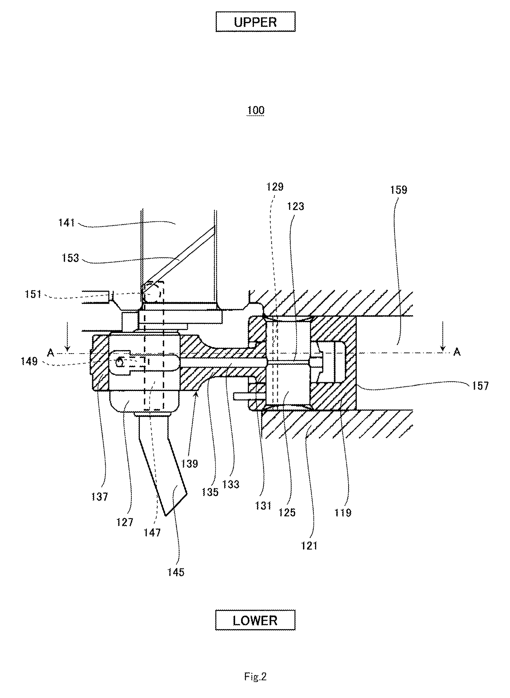
A refrigerant compressor comprises an electric element; a compression element; and a sealed container; wherein the compression element includes: a crankpin; a piston pin; and a connecting rod having a large hole portion into which the crankpin is inserted, a small hole portion in which the piston pin is rotatably disposed, and a coupling rod portion; wherein an oil guide hole is provided in the coupling rod portion of the connecting rod such that the large hole portion and the small hole portion are communicated with each other via the oil guide hole; a circular first groove is provided on an outer peripheral surface of the piston pin such that the first groove communicates with the oil guide hole; and a second groove extending in a center axis direction of the piston pin is provided in a first region of the small hole portion of the connecting rod.

Description

BACKGROUND OF THE INVENTION[0001]1. Field of the Invention[0002]The present invention relates to a refrigerant compressor used in a refrigeration cycle such as a refrigerator.[0003]2. Description of the Related Art[0004]As a refrigerant compressor used in a refrigeration cycle such as a refrigerator, there is a refrigerant compressor which includes a connecting rod attached with a crankpin and a piston pin at both ends thereof such that the crankpin and the piston pin are slidable, and converts an eccentric motion of the crankpin caused by a rotational motion of a crankshaft into a reciprocation motion of a piston, thereby obtaining a compression action. In the refrigerant compressor, the piston pin and a hole portion of the connecting rod are applied with a great surface pressure (load) during the compression action and thereby wear out.[0005]As a solution to this, a sealed compressor is known, which includes an oil feed hole extending inside of a connecting rod, and an oil feed gr...

Claims


Application Information

Patent Timeline
Patent Type & Authority Applications(United States)
IPC IPC(8): F04D27/00
CPCF04D27/00F04D27/02F04B39/00
Inventor KUBOTA, AKIHIKOSATO, JUNYAGI, AKIOMORISHIMA, MASATOMORI, YUJI
Owner PANASONIC APPLIANCES REFRIGERATION DEVICES SINGAPORE
Learn More