
Fluid pipe monitoring and reporting system

Inactive Publication Date: 2013-05-09
WATERSIGNAL
View PDF6 Cites 17 Cited by
  • Summary
  • Abstract
  • Description
  • Claims
  • Application Information

AI Technical Summary

Benefits of technology

The patent describes a system that can monitor the flow of fluid in a pipe and detect any leaks or other damage to the system. This system can work together with existing fluid monitors without interfering with them. By monitoring fluid flow continuously and reliably, the system can shorten the time it takes to respond to abnormal conditions. This system can help conserve water by providing real-time reporting of water flow data.

Problems solved by technology

This fluid flow information may reveal defects in the fluid system at a certain location, such as leaks in pipes, pools, internal plumbing, and other components of a fluid system.

Method used


Image

  • Fluid pipe monitoring and reporting system
  • Fluid pipe monitoring and reporting system
  • Fluid pipe monitoring and reporting system

Examples


example architecture

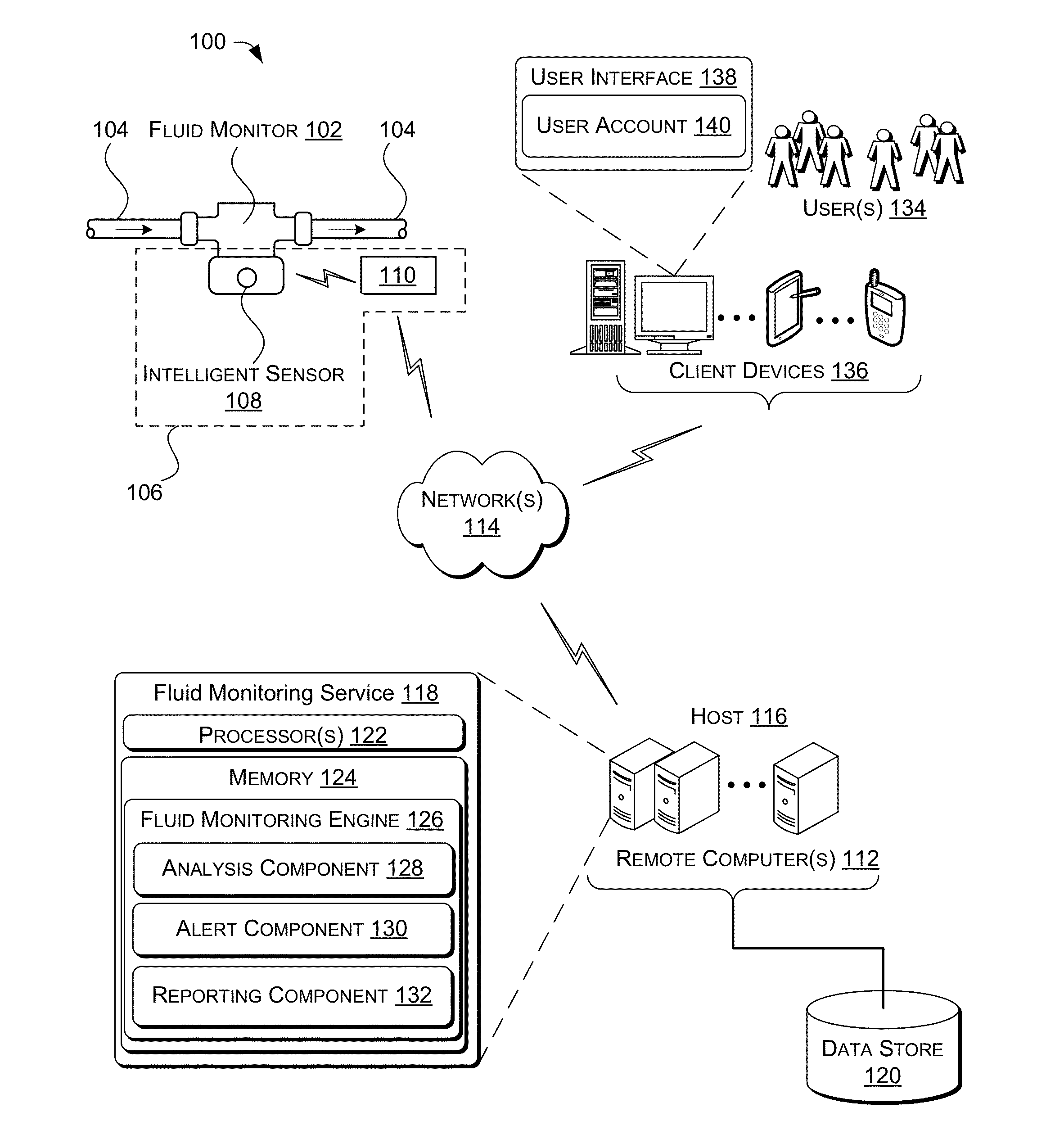
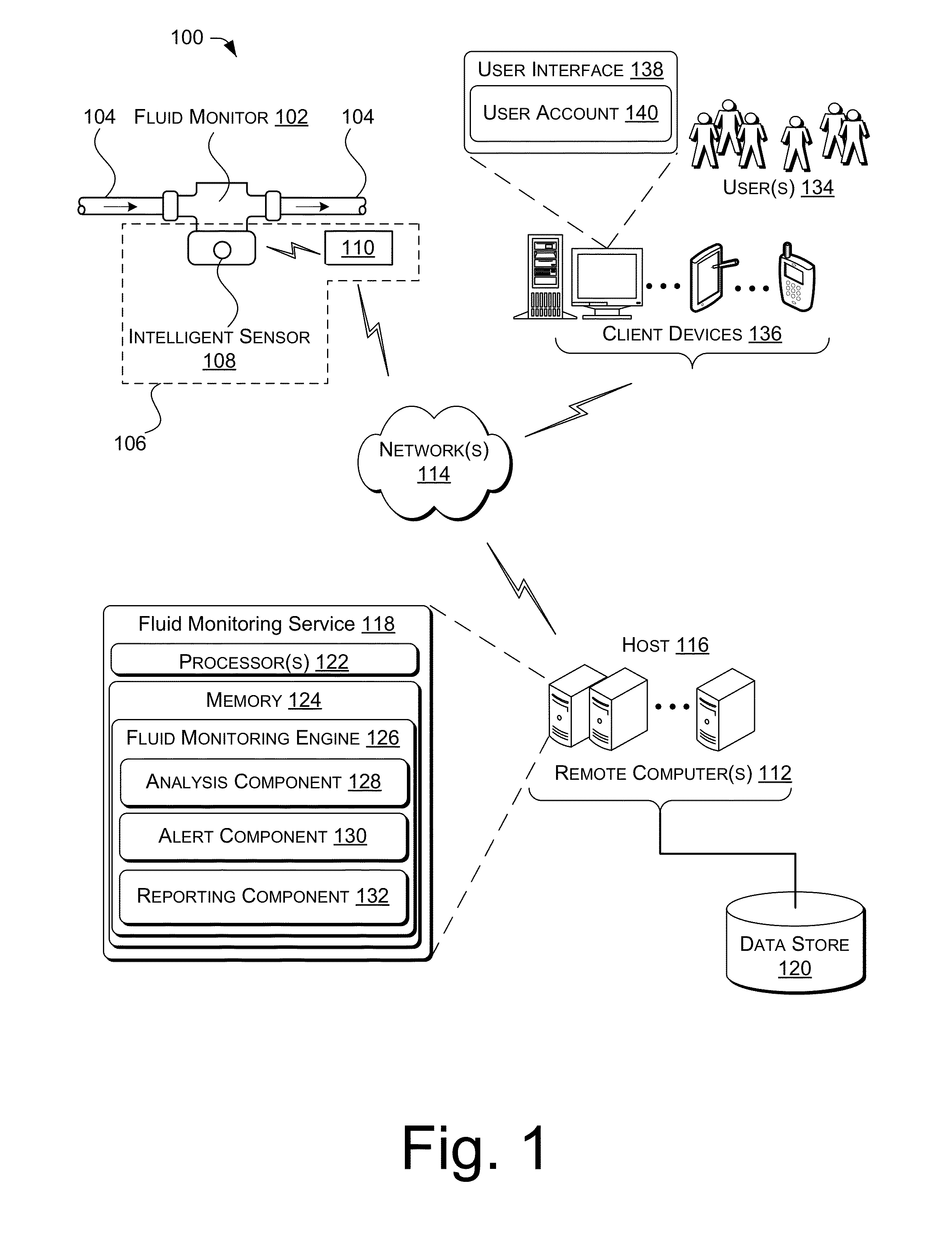
[0021]FIG. 1 illustrates an example of an architecture 100 of a fluid monitoring system for implementing a real-time fluid monitoring service. In the architecture 100, a fluid monitor 102, or flow meter, is configured to measure the amount of fluid that passes through a pipe 104. As used herein, the term “fluid” may comprise any substance that is capable of flowing, and that changes its shape when acted upon by a force. Fluids may include, but are not limited to, liquids, gases, plasmas or plastic solids such as water, sewage, nuclear waste, oil, molten metal, and the like. As shown in FIG. 1, fluid moves from left to right inside of the pipe 104. In some embodiments, the fluid monitor 102 may be a water meter and may include coupling magnets which rotate based on the amount of water that passes through the pipe 104. Each rotation of the coupling magnets represents a set amount of water that passes through the pipe 104. A fluid monitoring subsystem 106 may comprise an intelligent se...

example processes

[0047]FIG. 6 is a flow diagram of an illustrative process 600 for continuously monitoring fluid flow at a fluid monitor and sending data pertaining to fluid flow to a remote computer for analysis and reporting. The process is illustrated as a collection of blocks in a logical flow graph, which represent a sequence of operations that can be implemented in hardware, software, or a combination thereof. In the context of software, the blocks represent computer-executable instructions that, when executed by one or more processors, perform the recited operations. Generally, computer-executable instructions include routines, programs, objects, components, data structures, and the like that perform particular functions or implement particular abstract data types. The order in which the operations are described is not intended to be construed as a limitation, and any number of the described blocks can be combined in any order and / or in parallel to implement the process.

[0048]For discussion p...


PUM


Abstract

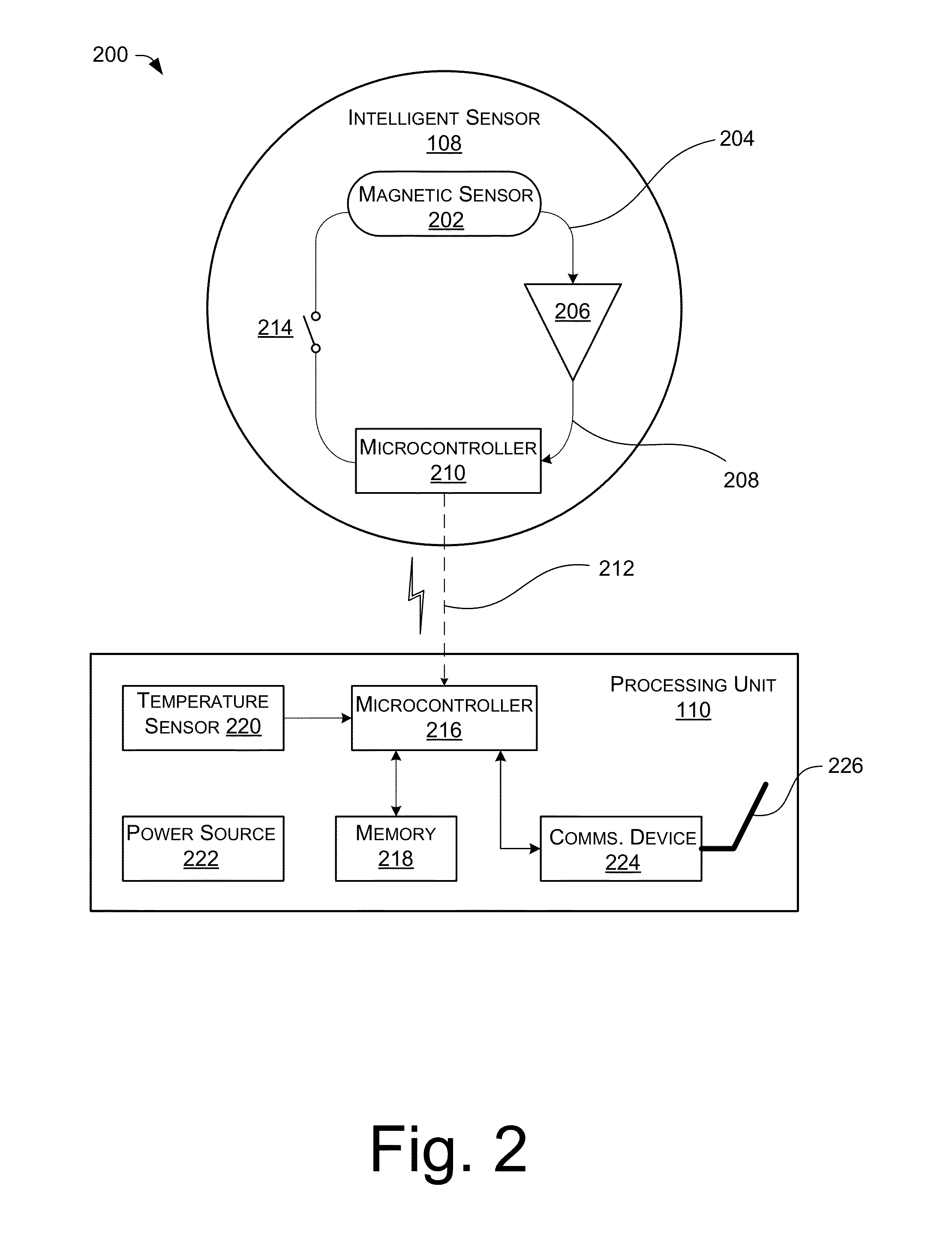
Disclosed herein is continuous fluid monitoring and reporting system. The continuous fluid monitoring and reporting system comprises a fluid monitoring subsystem comprising a processing unit configured to receive digital pulses indicative of a set amount of fluid that has flowed through a pipe and to count the digital pulses and store data comprising indications of the counted digital pulses in a memory. The stored data is periodically transmitted to a remote computer using a communication device. The remote computer includes a fluid monitoring engine to analyze the received data and to generate fluid flow information which may be used to generate reports and alerts to authorized users. In some embodiments, the fluid monitoring subsystem includes an intelligent sensor configured to obtain signals indicative of fluid flow at a fluid monitor and to output the digital pulses to the processing unit.

Description

RELATED APPLICATIONS[0001]This application is based on and claims priority to U.S. Provisional Application No. 61 / 555,749, filed on Nov. 4, 2011, by John Lie-Nielsen et al., entitled, “INTELLIGENT SENSOR FOR WATER METER,” the contents of which are herein incorporated by reference.BACKGROUND[0002]1. Field of the Invention[0003]The present invention relates generally to the monitoring of pipes containing a fluid for flow of the fluid. In particular, it is related to a water pipe leak monitoring and reporting system that can monitor water flow within a pipe at a water meter to detect a potential leak, and send data about the water flow within the pipe to a remote computer for analysis and reporting.[0004]2. Description of the Related Art[0005]Fluid monitors, or flow meters, measure the amount of fluid that flows through a pipe or an open conduit. Various techniques for measuring fluid flow exist and operate on differing principles. For instance, mechanical flow meters (e.g., displaceme...

Claims


Application Information

Patent Timeline
IPC IPC(8): G01F1/00G06F19/00
CPCG01F15/066G01F15/063
Inventor LIE-NIELSEN, JOHNSZENTI, TIBOR
Owner WATERSIGNAL
Learn More