
Spindle motor and method of manufacturing the same

a spindle motor and spindle technology, applied in the direction of dynamo-electric machines, instruments, supports/encloses/casings, etc., can solve the problems of increased workability and manufacturing costs, and increased risk of electrical leakage generation, so as to improve the insulation characteristics

Inactive Publication Date: 2013-05-09
SAMSUNG ELECTRO MECHANICS CO LTD
View PDF2 Cites 21 Cited by
  • Summary
  • Abstract
  • Description
  • Claims
  • Application Information

AI Technical Summary

Benefits of technology

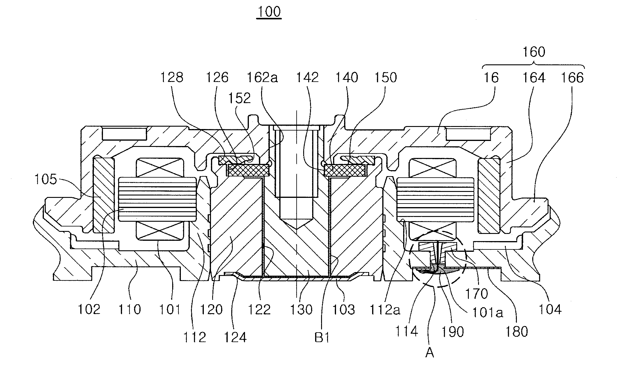
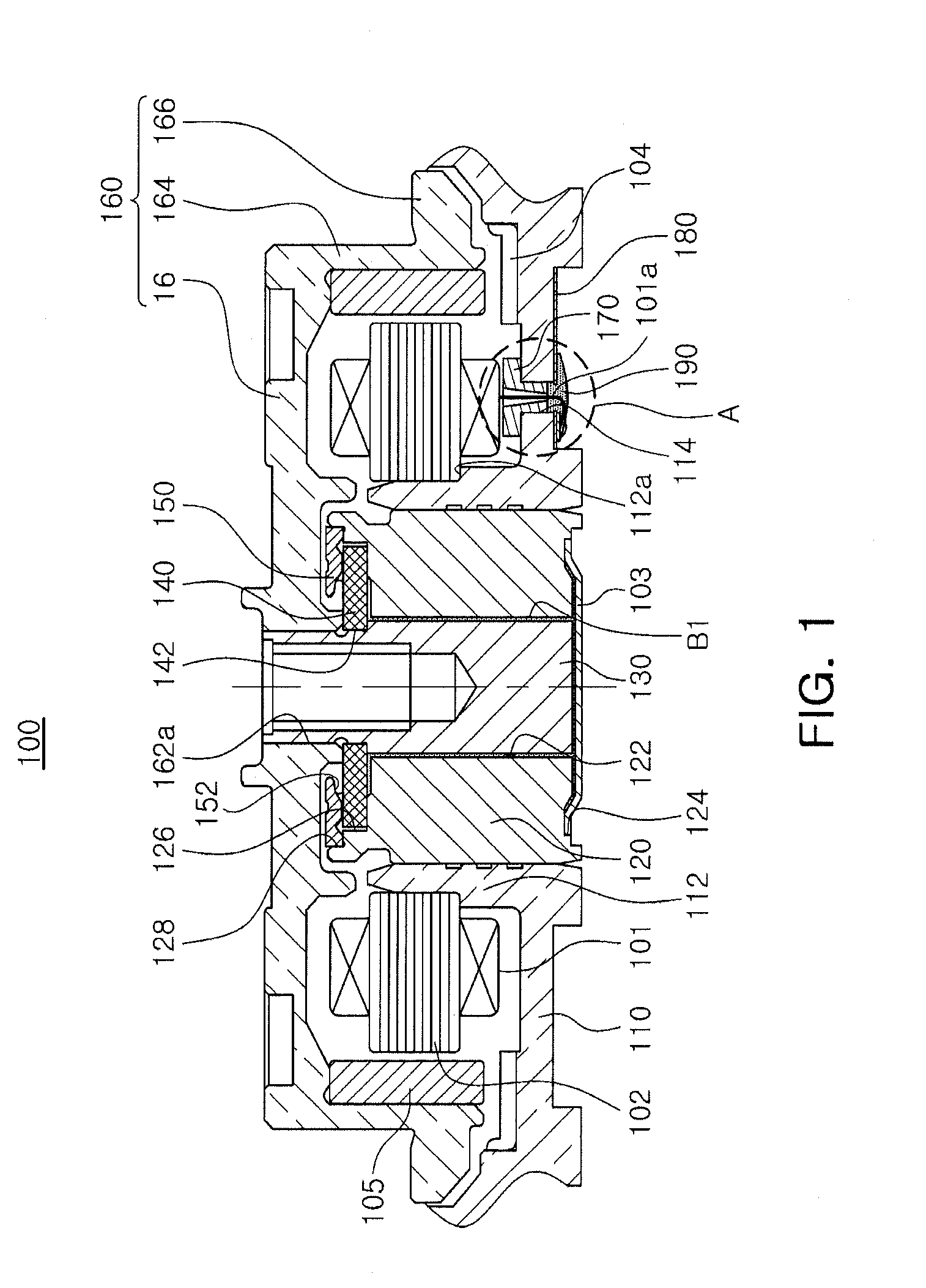
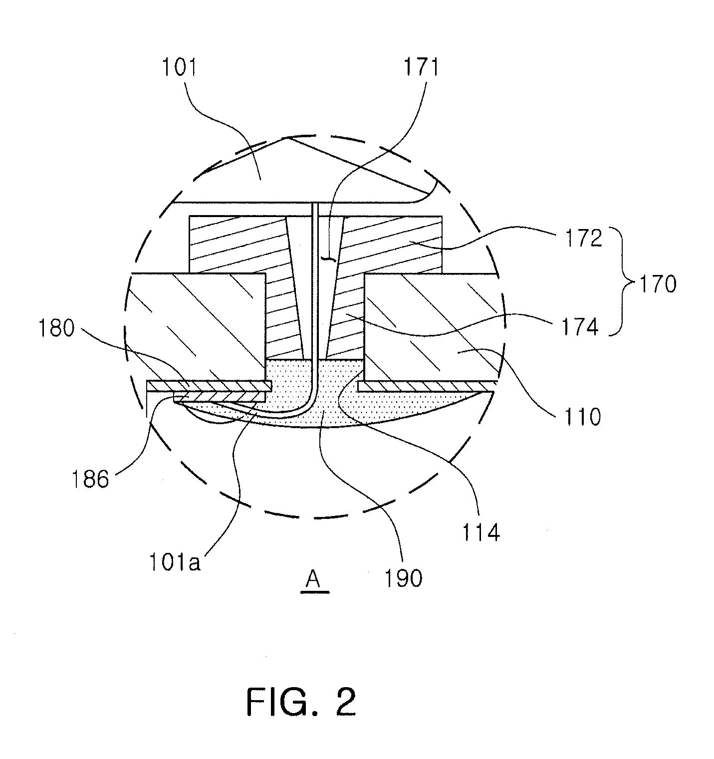
This patent describes a spindle motor with improved insulation and a method of manufacturing it at a reduced cost. It includes a base member with a through-hole, a circuit board with a communication hole, an insulating member inserted in the through-hole with a lead part of a coil, and a sealing member filling the space between the insulating member and the base member to close the through-hole. The installation hole of the insulating member has a wider diameter at the upper portion to facilitate the easy penetration of the lead part of the coil. The sealing member is made of an ultraviolet (UV) bonding material that can be easily introduced into the space between the insulating member and the base member during application.

Problems solved by technology

However, at the time of attachment and installation of the circuit board, electrical leakage may be generated according to a shape of a lower surface of the base or an installation state of the circuit board.
Further, a risk of electrical leakage generation increases in the case in which adhesion of the circuit board is weak or in the case in which a cold solder joint, or the like, is generated at the time of soldering of one end portion of the coil.
However, in the case of this method, workability and manufacturing costs may increase.
Further, even in the case in which the entire region of the lower surface of the circuit board is coated, the risk of electrical leakage may not be removed according to a bonding state of the circuit board.

Method used


Image

  • Spindle motor and method of manufacturing the same
  • Spindle motor and method of manufacturing the same
  • Spindle motor and method of manufacturing the same

Examples


Embodiment Construction

[0031]Embodiments of the present invention will now be described in detail with reference to the accompanying drawings. The invention may, however, be embodied in many different forms and should not be construed as being limited to the embodiments set forth herein. Rather, these embodiments are provided so that this disclosure will be thorough and complete, and will fully convey the scope of the invention to those skilled in the art.

[0032]Moreover, detailed descriptions related to well-known functions or configurations will be ruled out in order not to unnecessarily obscure subject matters of the present invention.

[0033]FIG. 1 is a schematic cross-sectional view showing a spindle motor according to an embodiment of the present invention; FIG. 2 is an enlarged view of part A of FIG. 1; and FIG. 3 is an exploded perspective view showing a base member and a circuit board of the spindle motor according to the embodiment of the present invention.

[0034]Referring to FIGS. 1 through 3, a sp...


PUM

PropertyMeasurementUnit
diameteraaaaaaaaaa

Abstract

There is provided a spindle motor including: a base member having a through-hole formed therein; a circuit board installed on a lower surface of the base member and including a communication hole formed therein to correspond to the through-hole; an insulating member insertedly disposed in the through-hole and having a lead part of a coil penetrating therethrough; and a sealing member filling a space formed by the insulating member insertedly disposed in the through-hole and the base member to thereby close the through-hole.

Description

CROSS-REFERENCE TO RELATED APPLICATIONS[0001]This application claims the priority of Korean Patent Application No. 10-2011-0114897 filed on Nov. 7, 2011, in the Korean Intellectual Property Office, the disclosure of which is incorporated herein by reference.BACKGROUND OF THE INVENTION[0002]1. Field of the Invention[0003]The present invention relates to a spindle motor and a method of manufacturing the same.[0004]2. Description of the Related Art[0005]A hard disk drive (HDD), an information storage device, writes data to a disk or reproduces data stored on a disk using a read / write head (hereinafter, referred to as a head).[0006]In hard disk drives, a head performs its function while being moved to a desired position by an actuator in a state in which it is suspended above a writing surface of a rotating disk at a predetermined height.[0007]Recently, as a portable electronic devices such as portable multimedia players (PMPs), personal digital assistants (PDAs), camcorders, MP3 player...

Claims


Application Information

Patent Timeline
Patent Type & Authority Applications(United States)
IPC IPC(8): H02K11/00H02K15/00
CPCH02K5/225H02K2203/15Y10T29/49009G11B19/2009H02K2211/03G11B19/20
Inventor LIM, TAE HYEONG
Owner SAMSUNG ELECTRO MECHANICS CO LTD
Learn More