Motor drive controller and control method

Inactive Publication Date: 2013-05-02
RICOH KK
View PDF1 Cites 47 Cited by
  • Summary
  • Abstract
  • Description
  • Claims
  • Application Information

AI Technical Summary

Benefits of technology

This patent describes a motor control system that uses multiple sensors to detect the position of a motor's rotor, and a signal converter to convert the sensor signals into a single-ended form. The system includes multiple detectors that compare the sensor signals to pre-determined levels to determine the rotor's phases. A phase divider then divides the phases into predetermined intervals, and a signal selector selects one of the sensor signals for each interval. A third detector then checks if the selected signal reaches a specific threshold level to indicate the position of the rotor. The system allows for precise detection and control of the motor's phases, even at high speeds.

Problems solved by technology

However, in this example of the motor drive controller, when a rotational velocity of the rotor changes in the hole-sensor edges, some error between an estimated rotary position change of the rotor and an actual rotary change may appear, and accurate phase information cannot be obtained.
However, in this example, although the motor drive controller can to some extent cope with rotary velocity change at the hole sensor edge interval due to use of an FG signal having smaller intervals than the hole sensor edge interval, doing so requires counting processors for counting the sensor signal and the FG signal, a FG signal generator or increment-type optical encoder, and a FG signal amplifier, all of which may increase the device size and cost of manufacture.
However, in this example, eight sensors are required, which for the small motor increases the installation space of the sensors and the cost.

Method used


Image

  • Motor drive controller and control method
  • Motor drive controller and control method
  • Motor drive controller and control method

Examples


first embodiment

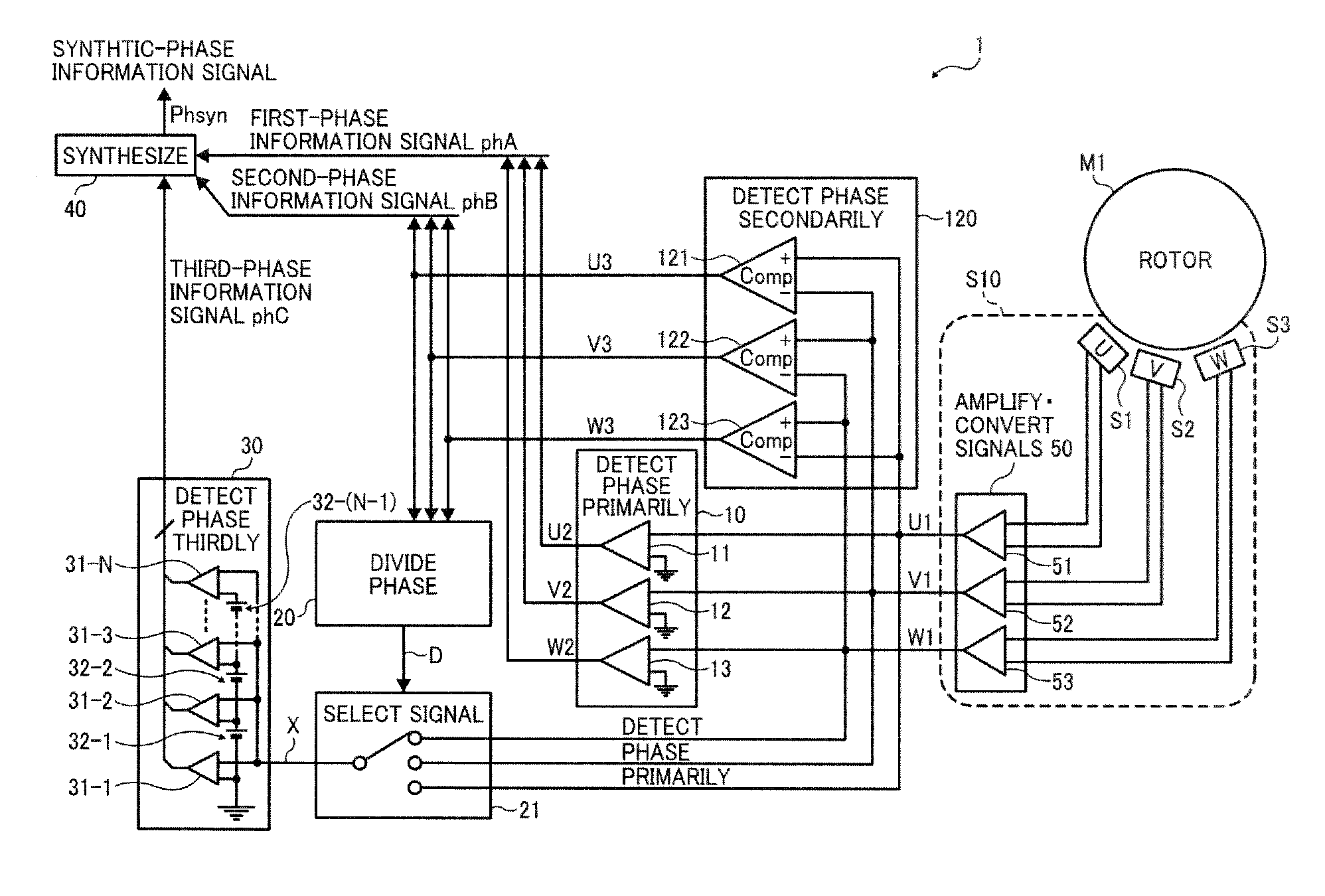
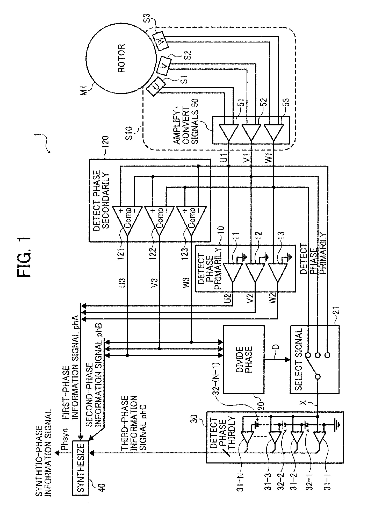
[0034]FIG. 1 is a block diagram illustrating a configuration of a motor drive controller 1 according to a first embodiment of the present disclosure.

[0035]In FIG. 1, a sensor integrated circuit (IC) S10 is provided around a rotor of a motor M1, and a motor driver controller 1 is connected to the motor M1 via the sensor IC S10. In the sensor IC, magnetic sensors (S1, S2, and S3) output differential sensor signals (U1, U1−; V1, V1−; and W1, −W1) and a signal amplifier-converter circuit 50 amplifies and converts the differential sensor signals (U1, U1−; V1, V1−; and W1, W1−) into amplified single-ended sensor signals (U1, V1, and W1). The motor driver controller 1 detects phase information of the motor M1 based on the amplified single-ended sensor signals (U1, V1, and W1) from the signal amplifier-converter circuit 50. The motor drive controller 1 includes a first phase-information detection circuit 10, a second phase-information detection circuit 120, a phase dividing circuit 20, a si...

second embodiment

[0066]FIG. 3A is a block diagram illustrating a configuration of a motor drive controller 1-A according to a second embodiment.

[0067]Compared with the motor driver controller 1 according to the first embodiment, the motor drive controller 1-A according to the second embodiment does not include the amplifier-converter circuit 50 to adjust and convert the amplitude of the differential sensor signals from the sensors S1, S2, and S3.

[0068]That is, a first phase-information detection circuit 10-A, a second phase-information detection circuit 120-A, and a signal selection circuit 21-A do not receive the single-ended signals (U1, V1, and W1) but directly receive the differential sensor signals (U1, U1−; V1, V1−; W1, W1−) from the sensors S1, S2, and S3 (U-phase, V-phase, and W-phase).

[0069]In the first phase-information detection circuit 10-A, the sensor signals U1 and U1− are input to a comparator 11-A, the sensor signals V and V1− are input to a comparator 12-A, and the sensor signals W1...

third embodiment

[0099]FIG. 7 is a block diagram illustrating a configuration of a motor drive controller 1-C according to a third embodiment.

[0100]Compared with the motor drive controller 1-B according to the variation of the second embodiment, the motor drive controller 1-C according to the third embodiment includes a motor driver 70 to selectively send driving currents to multiple motor coils to drive rotating the rotary of the motor M1; and a motor controller 60 to generate pulse width modulation (PWM) signal based on the second phase information signal phB and output the PWM signal to the motor driver 70. The other configuration is similar to the first embodiment, and the description thereof is omitted.

[0101]FIG. 8 is a circuit diagram illustrating a configuration of the motor driver 70 shown in FIG. 7. In FIG. 8, the motor driver 70 includes a pre-driver 80 and a main-driver 90. For example, three-phase coils (U-Phase, V-Phase, and W-Phase) to drive the motor M1 that is a brushless DC motor, a...


PUM


Abstract

A motor drive controller to control a motor via multiple sensors includes a first phase detector to compare respective differential pairs of the sensor signals from the same sensor to detect phases of the rotor, and output a first phase information signal; a second phase detector to compare a respective one of the multiple sensor signals with another sensor signal from the different sensor to detect the phases and output a second phase information signal; a phase divider to divide the phases, detected by the first and second phase detectors, into multiple predetermined phase intervals; a signal selector to select one of the multiple sensor signals in the multiple predetermined phase intervals; and a third phase detector to detect whether the signal selected by the signal selector reaches a predetermined threshold level corresponding to a predetermined phase of the rotor, and output a third phase information signal.

Description

CROSS-REFERENCE TO RELATED APPLICATION[0001]This patent application is based on and claims priority pursuant to 35 U.S.C. §119 to Japanese Patent Application No. 2011-237171, filed on Oct. 28, 2011 in the Japan Patent Office, the entire disclosure of which is hereby incorporated by reference herein.FIELD[0002]1. Technical Field[0003]The present disclosure relates to a motor drive controller including a phase detector to detect a phase of a rotor of a motor, and more particularly, to a motor drive controller employing a control method that drives the motor using the readings from a phase detector.[0004]2. Description of the Related Art[0005]When a rotary position of a motor is controlled, it is necessary to detect a rotational angle of the rotor. In general, relative rotational angle of the rotor is detected by connecting a rotary shaft of the motor to a rotary encoder, outputting a two-phase pulse signal having a phase difference of a quarter cycle that changes with the rotational a...

Claims


Application Information

Patent Timeline
IPC IPC(8): H02P6/16G01D5/244H02P6/06H02P6/08
CPCH02P6/16
Inventor KAMATANI, TOMOHIKOSUZUKI, HARUYUKISHIMIZU, FUMIHIROFURUSE, KATSUHISA
Owner RICOH KK
Why Eureka
Try Eureka