
Processing machine system and method of positioning processing machines

a processing machine and positioning technology, applied in the direction of machine supports, manufacturing tools, transportation and packaging, etc., can solve the problems of reducing the transfer accuracy, difficult to set the sum of impulses to zero without adversely affecting other apparatuses, increasing costs, etc., to reduce the space occupied by processing machines and suppress the effect of vibration transfer

Active Publication Date: 2013-04-25
CANON KK
View PDF9 Cites 2 Cited by
  • Summary
  • Abstract
  • Description
  • Claims
  • Application Information

AI Technical Summary

Benefits of technology

The invention is a system of processing machines that saves space and reduces vibration transfer between them. The technical effects are that this system takes up less space and minimizes the transfer of vibration between the processing machines.

Problems solved by technology

Unfortunately, juxtaposing processing machines often have a trade-off relationship with the transfer accuracy.
However, when vibrational forces from other imprint apparatuses are transferred to a specific imprint apparatus, the interface at which the mold is in contact with the uncured resin becomes unstable, thus degrading the transfer accuracy.
However, to set the sum of the impulses of the apparatuses to zero, it is necessary to take into consideration, for example, the number, positions, and rotational components of apparatuses, and the frequency components of generated vibrational forces, thus making it difficult to set the sum of the impulses to zero without adversely affecting other apparatuses.
When a complex control system is provided to set the sum of the impulses to zero, it leads to an increase in cost.
However, simply setting large distances between the processing machines poses a problem resulting from a decrease in number of apparatuses arranged per unit area.

Method used


Image

  • Processing machine system and method of positioning processing machines
  • Processing machine system and method of positioning processing machines
  • Processing machine system and method of positioning processing machines

Examples


Embodiment Construction

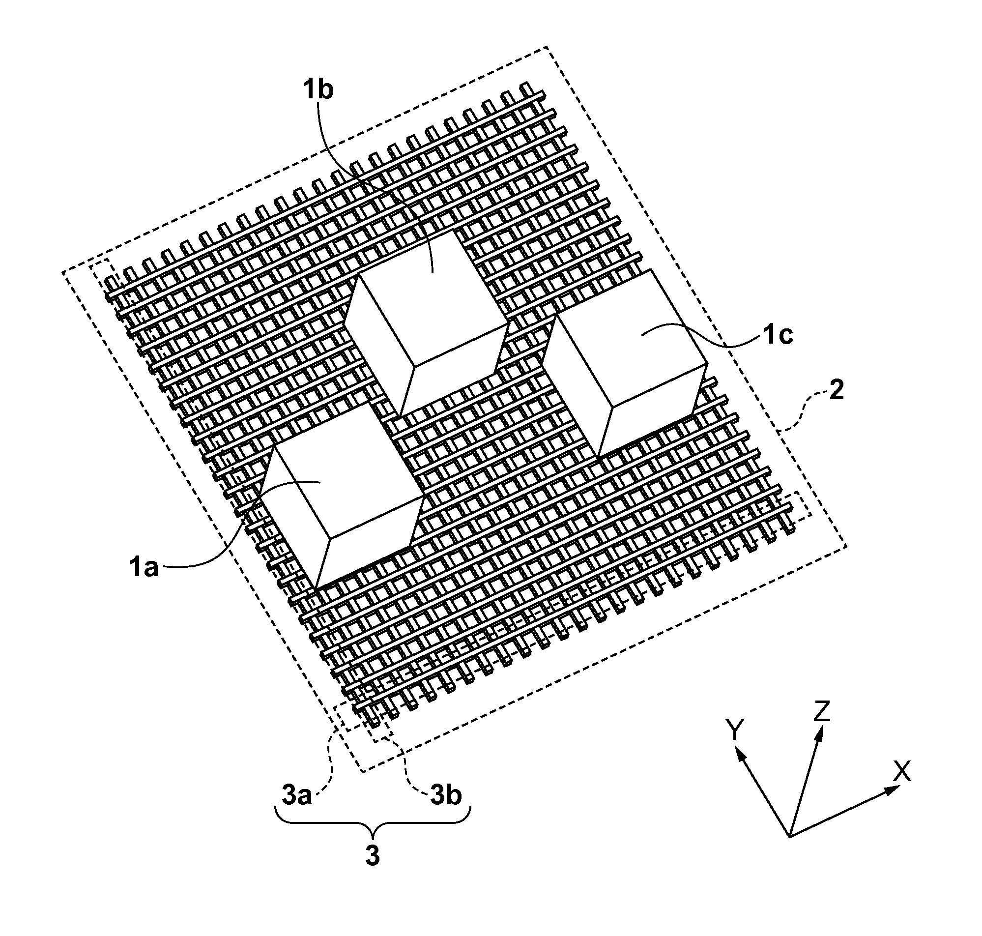
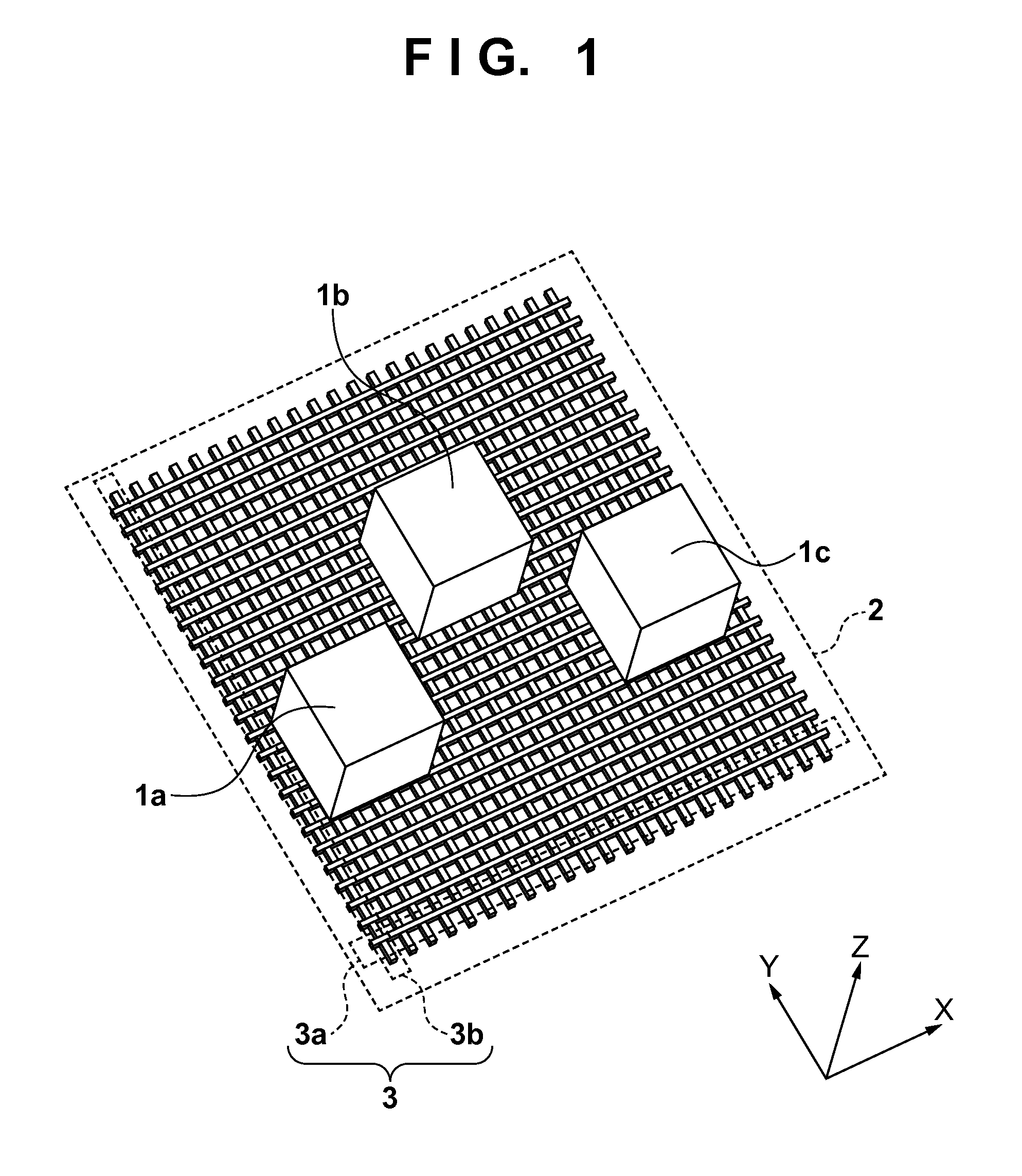
[0019]A cluster processing machine system including a plurality of processing machines according to an embodiment of the present invention will be described below with reference to the accompanying drawings. Note that the “cluster processing machine system” in this embodiment means a system including a plurality of processing machines which are juxtaposed on the same supporting structure and simultaneously manufacture articles such as devices, in order to ensure a given productivity and save space. The supporting structure according to the present invention means a floor which includes beams and to which processing machines are fixed through a pedestal provided in each processing machine.

[0020]FIG. 1 is a schematic view showing a processing machine system in this embodiment. The processing machine system includes three processing machines 1a, 1b, and 1c and a supporting structure 2 which supports them. Upon defining the first processing machine 1a as a first processing machine, the ...


PUM

PropertyMeasurementUnit
distanceaaaaaaaaaa
transfer speedaaaaaaaaaa
vibrational forcesaaaaaaaaaa

Abstract

At least three processing machines are positioned on a supporting structure including a plurality of beams spaced apart from each other. The at least three processing machines include a first processing machine, a second processing machine supported by at least one of beams which support the first processing machine, and a third processing machine supported by beams different from all the beams which support the first processing machine. A distance between the first processing machine and the second processing machine, at which an amount of vibration transferred from the first processing machine to the second processing machine becomes smaller than a predetermined amount, is determined, thereby positioning the first processing machine and the second processing machine with a distance not less than the determined distance.

Description

BACKGROUND OF THE INVENTION[0001]1. Field of the Invention[0002]The present invention relates to a processing machine system and a method of positioning processing machines.[0003]2. Description of the Related Art[0004]In recent years, as a technique of manufacturing a semiconductor device, a fine patterning technique in which a mold is pressed against an uncured resin on a substrate to transfer a fine three-dimensional pattern formed on the mold onto the substrate is attracting a great deal of attention. This technique is called an imprint technique, which can form a fine structure on the order of several nanometers on a substrate. The photo-curing method, for example, is available as one of imprint techniques. In an imprint apparatus which adopts the photo-curing method, first, an ultraviolet-curing resin is coated (dispensed) on an imprint region on a substrate, and a mold is pressed against the resin. After the resin is cured upon irradiation with ultraviolet rays, the mold is re...

Claims


Application Information

Patent Timeline
Patent Type & Authority Applications(United States)
IPC IPC(8): F16M7/00B29C69/00B21B15/00B29C35/08
CPCB21B15/00B29C35/08B29C69/00Y10T29/51F16M5/00F16M7/00H01L21/00F16F15/00H01L21/0273B23Q1/01
Inventor OKADA, TETSUJIEMOTO, KEIJIHASEGAWA, NORIYASU
Owner CANON KK
Learn More