
Coiled Tubing Injector with a Weight on Bit Circuit

a technology of injectors and weights, applied in the field of hydraulic circuits, can solve problems such as slow penetration ra

Active Publication Date: 2013-04-25
XTREME COIL DRILLING
View PDF3 Cites 1 Cited by
  • Summary
  • Abstract
  • Description
  • Claims
  • Application Information

AI Technical Summary

Benefits of technology

The system ensures a consistent weight-on-bit across different drilling conditions by bypassing the counterbalance valve, allowing for controlled upward force application, reducing the risk of system failure and improving drilling efficiency by maintaining a constant weight-on-bit, even when encountering obstacles or softer formations.

Problems solved by technology

If the drill bit encounters a more difficult formation, the rate of penetration will slow.

Method used


Image

  • Coiled Tubing Injector with a Weight on Bit Circuit
  • Coiled Tubing Injector with a Weight on Bit Circuit
  • Coiled Tubing Injector with a Weight on Bit Circuit

Examples


Embodiment Construction

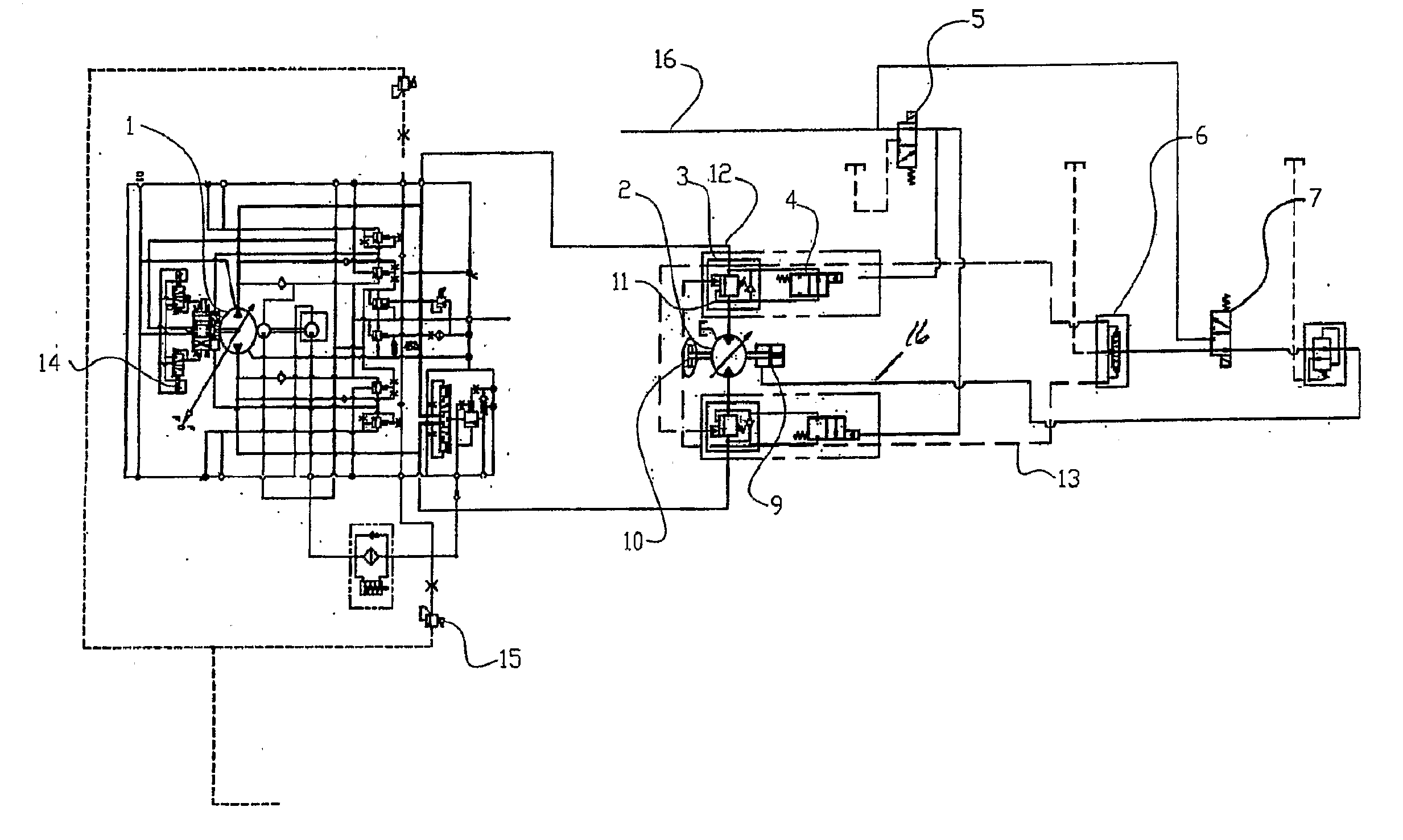
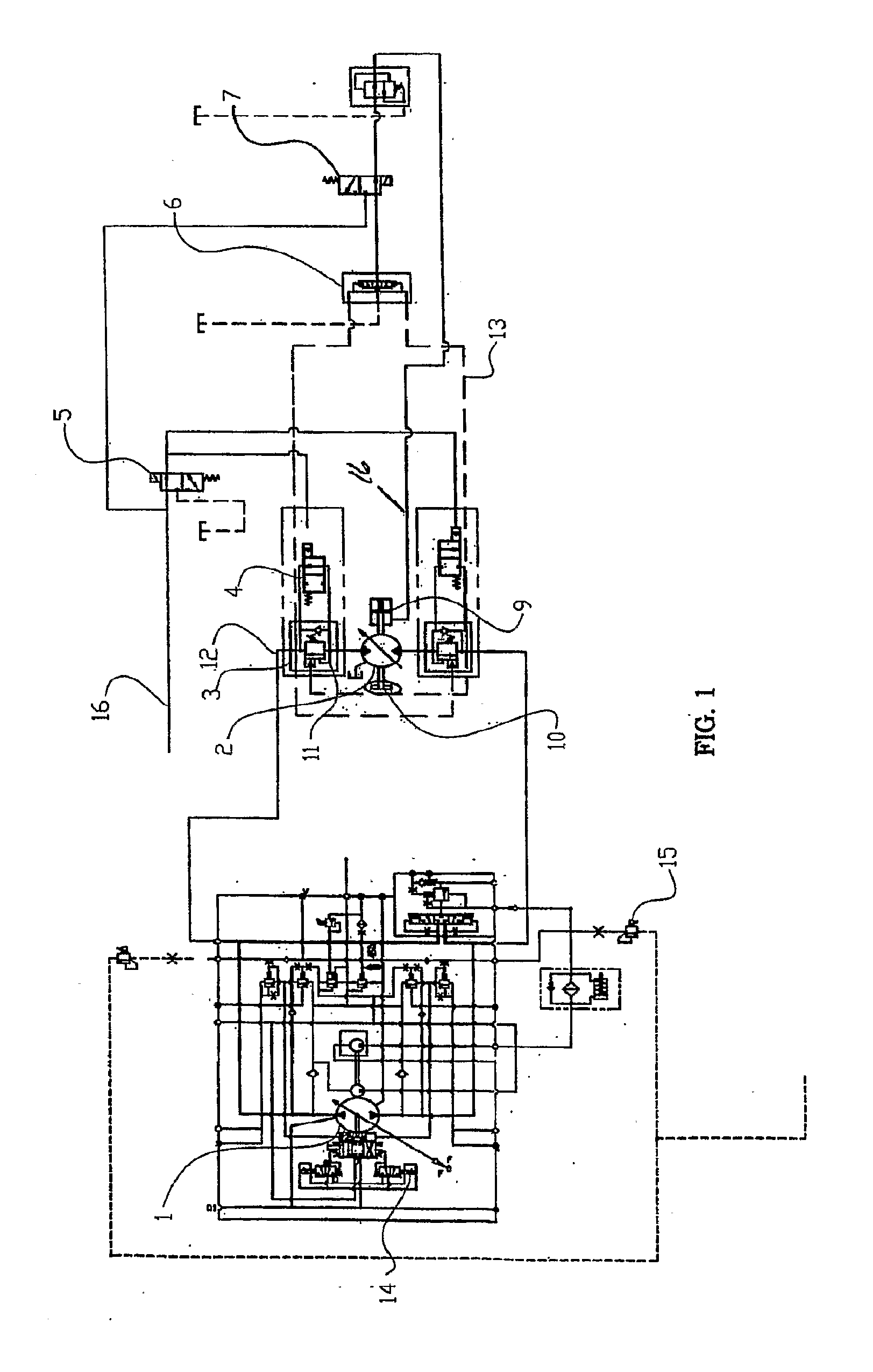
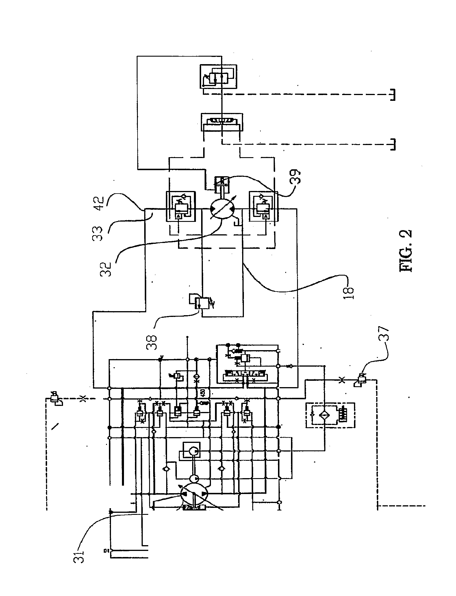
[0018]In one embodiment, an injector feeds coiled tubing into the well bore using a hydraulic motor to power the chains that carry the gripper blocks. At equilibrium, the’ hydraulic motor is holding the drilling string with a given pressure, e.g., approximately 2000 psi. That pressure may be supplied by a variable displacement, variable pressure hydraulic pump. The pump will thus be supplying 2000 psi pressure to the hydraulic motor, but there would be no flow of hydraulic fluid. The motor is stationary and holding the load by the supplied pressure.

[0019]The hydraulic circuit incorporates a counterbalance valve. The function of this valve is to prevent the load (the drill string) from descending into the well bore unless the injector circuit controller is in the “in-hole” mode. Selecting the in-hole mode opens the counterbalance valve, allowing the hydraulic motor to power the drill string into the borehole, The counterbalance valve also serves the function of a safety device. Shoul...


PUM


Abstract

A control circuit for a coiled tubing injector includes a circuit controller (14). One or more counterbalance vales (3) may be responsive to the circuit controller to prevent the tubing string from descending into the wellbore during rate of penetration movement. In one embodiment, a control valve (4) allows fluid to flow through a bypass line around the counterbalance valves when drilling in a weight-on-bit mode. Other hydraulic control circuits allow for the release of fluid pressure to control the injector hydraulic motor. In yet another embodiment, the control circuit regulates power to an electric motor of the injector.

Description

CROSS REFERENCE TO RELATED APPLICATION[0001]This application is a divisional of U.S. Ser. No. 12 / 441,746, filed on Mar. 18, 2009, which is a U.S. national phase of PCT / US2007 / 020585, filed Sep. 24, 2007, which claims the priority of U.S. Provisional Application No. 60 / 846,721 filed on Sep. 22, 2006, the disclosures of which are incorporated herein by reference for all purposes.FIELD OF THE INVENTION[0002]The present invention relates to coiled tubing of injectors of a type commonly used in oilfield operation to raise or lower coiled tubing into a well. More particularly, the invention relates to a hydraulic circuit for controlling the drive motors of a coiled tubing injector so as to more reliably control weight on bit at various depths.BACKGROUND OF THE INVENTION[0003]Coiled tubing injectors have been used for years to inject coiled tubing into a well, while a drawworks and / or a top drive are conventionally used for raising and lowering threaded tubulars into a well. In either case...

Claims


Application Information

Patent Timeline
Patent Type & Authority Applications(United States)
IPC IPC(8): F16D31/02
CPCE21B19/22F16D31/02E21B44/02
Inventor HAVINGA, RICHARD
Owner XTREME COIL DRILLING
Learn More