Ultraviolet lamp system and method for controlling emitted ultraviolet light

a technology of ultraviolet light and ultraviolet lamp, which is applied in the direction of electric discharge lamps, energy-saving lighting, sustainable buildings, etc., can solve the problems of inoperable sensors, prone to solarization, and substantial constant uv light intensity,

Inactive Publication Date: 2013-04-18
NORDSON CORP
View PDF6 Cites 19 Cited by
  • Summary
  • Abstract
  • Description
  • Claims
  • Application Information

AI Technical Summary

Problems solved by technology

Providing a substantially constant UV light intensity presents some challenges.
These sensors measure the UV light intensity of the light source once and cannot indicate the UV light intensity from successive applications without interrupting the use of that light source.
Moreover, such sensors are often prone to solarization due to the constant exposure to high intensity UV light, rendering them inoperable.
Still further, such methods are typically performed by the lamp system customer or the lamp system vendor during setup and / or maintenance, which are disruptive to the use of the UV lamp systems.
Such methods also require significant time by the customer to configure future UV intensities that can be used for their applications that will “degrade gracefully” as those UV lamp systems decrease in their intensity.
But these maintenance schedules also significantly interrupt the use of the UV lamp system, because any processing of substrates is halted to perform any maintenance or testing.
Moreover, these maintenance schedules generally fail to take into account and adjust for degradation and / or contamination of the UV lamp system between various applications and / or substrates.
This is often a problem for applications that require a high degree of consistency.

Method used


Image

  • Ultraviolet lamp system and method for controlling emitted ultraviolet light
  • Ultraviolet lamp system and method for controlling emitted ultraviolet light
  • Ultraviolet lamp system and method for controlling emitted ultraviolet light

Examples


Embodiment Construction

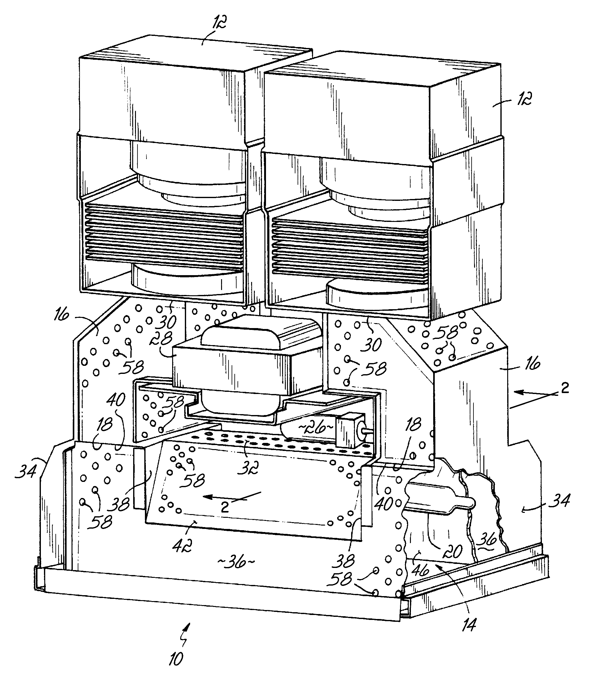
[0023]In general, there are variations in the power output of magnetrons used in ultraviolet (UV) lamp systems, contamination that occurs on the UV bulb or reflector of UV lamp systems, and degradation of components of the UV lamp system. Thus, there are often variations in the UV radiation or light produced due to those factors. These variations, in turn, directly correlate to variations in the UV light intensity from the UV lamp system. This creates difficulties for some applications that are sensitive to changes in the intensity of UV light, and in particular critical processes that tend to require consistent UV light intensity.

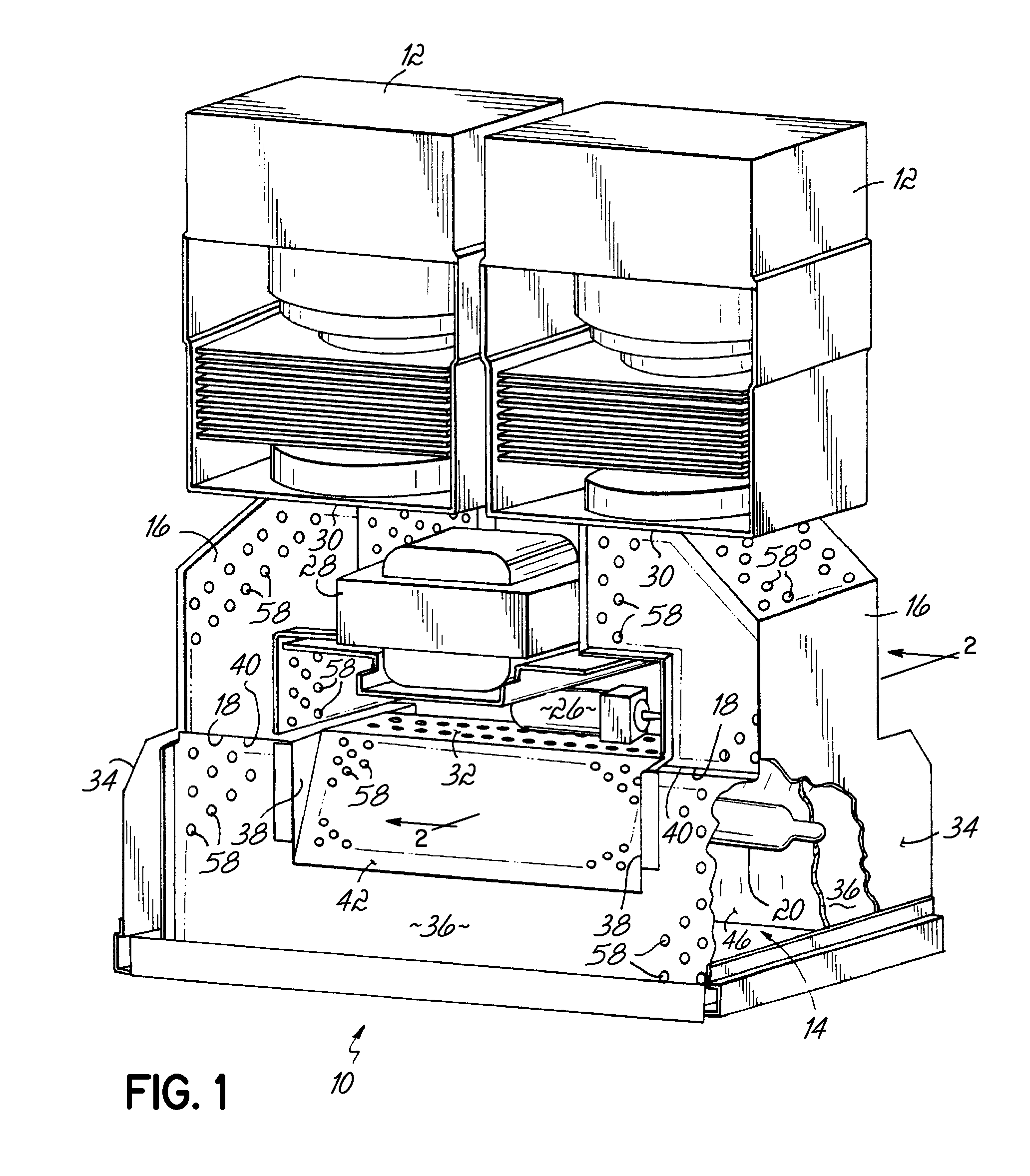
[0024]Turning now to the drawings, wherein like numbers denote like parts throughout the several views, FIG. 1 shows a microwave excited UV lamp system or light source 10 is shown consistent with embodiments of the invention. Light source 10 includes a pair of microwave generators, illustrated as a pair of magnetrons 12, that are each coupled to a longitud...


PUM


Abstract

Embodiments of the invention provide an apparatus, method, and program product to control a lamp system. The apparatus comprises a plasma lamp bulb (20) and a microwave generator (12) operable to generate a microwave energy field to excite the plasma lamp bulb (20) to emit ultraviolet light (24). The apparatus further comprises a sensor (70) to measure the intensity of the ultraviolet light (24) and a reflector (42) positioned between the plasma lamp bulb (20) and the sensor (70) The reflector (42) is operable to reflect at least a portion of the ultraviolet light (24) generated by the plasma lamp bulb (20). The method comprises receiving a target intensity for the ultraviolet light (24) and measuring an intensity of the ultraviolet light (24) using a sensor (70). The method further comprises comparing the target intensity to the measured intensity and, in response to the comparison, adjusting power to a microwave generator (12) to adjust the intensity of the ultraviolet light (24).

Description

FIELD OF THE INVENTION[0001]The present invention relates generally to ultraviolet lamp systems and, more particularly, to regulation of microwave-excited ultraviolet lamp systems.BACKGROUND OF THE INVENTION[0002]Ultraviolet (UV) lamp systems are commonly used for heating and curing materials such as adhesives, sealants, inks, and coatings. Certain UV lamp systems have electrodeless light sources and operate by exciting an electrodeless plasma lamp with microwave energy. In an electrodeless UV lamp system that relies upon excitation with microwave energy, the electrodeless plasma lamp is mounted within a metallic microwave cavity or chamber. One or more microwave generators, such as magnetrons, are coupled via waveguides with the interior of the microwave chamber. The magnetrons supply microwave energy to initiate and sustain a plasma from a gas mixture enclosed in the plasma lamp. The plasma emits a characteristic spectrum of electromagnetic radiation strongly weighted with spectra...

Claims


Application Information

Patent Timeline
Patent Type & Authority Applications(United States)
IPC IPC(8): H05B41/38
CPCH05B41/2806Y02B20/22H05B41/38H01J65/044Y02B20/00
Inventor BORSUK, JAMES M.KHOURY, JAMESMCGHEE, EDWARD C.SMITH, JAMES
Owner NORDSON CORP
Why Eureka
Try Eureka