Positioning apparatus of cam plate for vehicular air conditioning system

a technology of vehicular air conditioning system and positioning apparatus, which is applied in vehicle components, vehicle heating/cooling devices, transportation and packaging, etc., can solve the problems of increasing effort and quality problems, and achieve the effects of reducing effort, eliminating engagement, and improving snapping feeling

Inactive Publication Date: 2013-04-18
HANON SYST +2
View PDF4 Cites 1 Cited by
  • Summary
  • Abstract
  • Description
  • Claims
  • Application Information

AI Technical Summary

Benefits of technology

The present invention is about a positioning apparatus for a cam plate that can reduce the effort and effortlessness of air conditioning modes. By eliminating a steep slope in a guide slot formed in the cam plate, the apparatus can create a secure and snapping feeling during operation. This results in a more comfortable and efficient air conditioning experience. Overall, the technical effect of the invention is to improve the performance and user experience of air conditioning devices.

Problems solved by technology

As a result, since the feeling when being operated is degraded due to the presence of the inflection section, there are disadvantages such as requiring more effort and causing a quality problem due to the feeling when engaged.

Method used


Image

  • Positioning apparatus of cam plate for vehicular air conditioning system
  • Positioning apparatus of cam plate for vehicular air conditioning system
  • Positioning apparatus of cam plate for vehicular air conditioning system

Examples


Embodiment Construction

[0031]Reference will now be made in detail to various embodiments of the present invention(s), examples of which are illustrated in the accompanying drawings and described below. While the invention(s) will be described in conjunction with exemplary embodiments, it will be understood that the present description is not intended to limit the invention(s) to those exemplary embodiments. On the contrary, the invention(s) is / are intended to cover not only the exemplary embodiments, but also various alternatives, modifications, equivalents and other embodiments, which may be included within the spirit and scope of the invention as defined by the appended claims.

[0032]Hereinafter, the positioning apparatus of the cam plate for the vehicular air conditioning system according to the exemplary embodiment of the present invention will be described in detail by referring to the accompanying drawings.

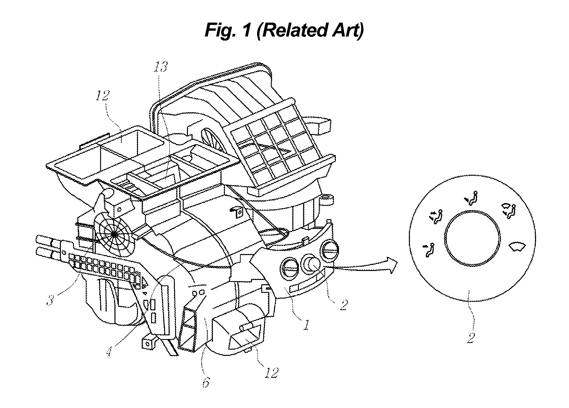
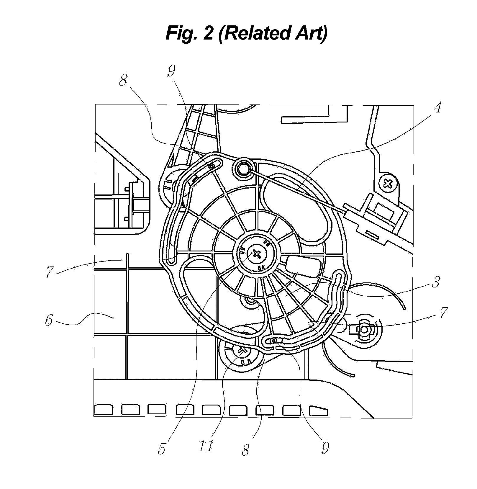
[0033]In an air conditioning system in which a regulating knob 2 (illustrated in FIG. 1) for se...


PUM


Abstract

A positioning apparatus of a cam plate for a vehicular air conditioning system may include the cam plate rotatably coupled to an air conditioning case by a cam shaft and including a guide slot, a plurality of positioning holes formed in the cam plate, a detent mechanism projecting from the air conditioning case toward the cam plate, and an arm rotatably coupled to the air conditioning case and including a connecting pin that may be slidably coupled to the guide slot of the cam plate, wherein, while the cam plate rotates about the cam shaft and the connecting pin included in the arm performs a camming action along the guide slot formed in the cam plate, a leading end of the detent mechanism may be selectively inserted into one of the positioning holes to detent the position of the cam plate when the connecting

Description

CROSS-REFERENCE TO RELATED APPLICATIONS[0001]The present application claims priority to Korean Patent Application No. 10-2011-0105743 filed on Oct. 17, 2011, the entire contents of which is incorporated herein for purposes by this reference.BACKGROUND OF THE INVENTION[0002]1. Field of the Invention[0003]The present invention relates to a positioning apparatus of a cam plate for a vehicular air conditioning system, and more specifically, relates to a positioning apparatus of a cam plate for a vehicular air conditioning system capable of eliminating an idling section of the cam plate in each of the air conditioning modes.[0004]2. Description of Related Art[0005]Generally, as illustrated in FIG. 1, a control panel 1 for controlling an air conditioning system is provided in an instrument panel of a vehicle. The control panel 1 is provided with a regulating knob 2 for selecting an air conditioning mode.[0006]The front surface of the regulating knob 2 has symbols formed on it that corresp...

Claims


Application Information

Patent Timeline
Patent Type & Authority Applications(United States)
IPC IPC(8): F16H53/00
CPCY10T74/2101B60H1/00857B60H1/00B60H1/12B60H1/32
Inventor LEE, YOON HYUNGPARK, TAE YONG
Owner HANON SYST
Why Eureka
Try Eureka