Eureka AIR delivers breakthrough ideas for toughest innovation challenges, trusted by R&D personnel around the world.

Use of nanoparticles for labelling oil field injection waters

a technology of oil field injection water and nanoparticles, which is applied in the direction of radiation measurement, optical radiation measurement, spectral modifiers, etc., can solve the problems of not being able to multi-label or repeat the same labeling, requiring a rather complex and expensive process, and difficult to detect nacl chloride used as tracer

Inactive Publication Date: 2013-04-04
TOTAL PUTEAUX FR
View PDF13 Cites 109 Cited by
  • Summary
  • Abstract
  • Description
  • Claims
  • Application Information

AI Technical Summary

Benefits of technology

The patent describes a new way to study solid materials like oil reservoirs by using a liquid to diffuse through them. This method is simple and economical, and it can also quickly and easily analyze very small amounts of tracer agents present in the oil. The technique can also purify and separate the tracers from the oil residues, and it has good sensitivity and can extract the fluorescence signal of the tracers easily. The method uses time-resolved fluorescence detection, which eliminates unwanted signals and measures only the relative amount of tracer.

Problems solved by technology

For example, an aqueous solution of sodium chloride cannot be used as tracer since most of the oilfields contain sea water, and thus a substantial quantity of sodium chloride, which makes detecting NaCl chloride used as tracer particularly difficult;furtive tracer, that is, not easily absorbed in the solid medium traversed or eliminated from the tracing fluid, since with the analytical technique used, the tracer concentration in the fluids produced at the exit is determined and compared with that of the fluids injected in the injection well(s);the tracer resists bacterial contamination, high temperatures and high pressures present in oil reservoirs;the tracer has the ability to interact or not interact with the medium of the reservoir, namely, the geological media, oil-bearing or not;access to a great number of tracers and different codings for possible simultaneous detections (several injection wells) or tracing test which are successive over time.
However, they have three major drawbacks:their quantification requires a rather complex and expensive process and can be carried out only in a specialized center, often far away from productions sites;these molecules, which are not numerous, do not allow for multi-labeling or repeated labelings;some of these known tracers are caused to disappear due to their negative impact on the medium.
However, to date, no study has shown the feasibility of the detection of particles for oil tracing.
It seems to be even generally accepted that particles, due to the volume of space they fill, are filtered and strongly retained in the soil, thus preventing any reasonable use of their detection as tracing.

Method used


Image

  • Use of nanoparticles for labelling oil field injection waters
  • Use of nanoparticles for labelling oil field injection waters
  • Use of nanoparticles for labelling oil field injection waters

Examples


example 1

Particles Prepared According to the Example of Preparation 1; Naked SiO2 Surface

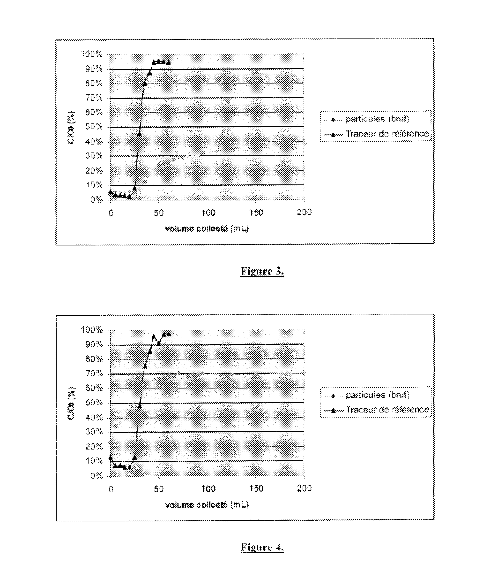
[0134]This example is a test of diffusion through a porous core cartridge according to preparation 8. The porous core is of the DU30804 type and has the following characteristics:[0135]Nature of the material: sandstone[0136]Dimensions: 4 to 5 cm in diameter; 10 to 13 cm in length[0137]Permeability: 250 to 500 mDa[0138]Porosity: 20%

[0139]The suspension of nanoparticles has been obtained according to preparation 9. The flow rate imposed by the pump is 20 mL / hour. The fractions recovered at the exit of the rock have a volume of 5 mL.

[0140]FIG. 3 shows the comparative curves of diffusion between the reference tracer (yellow) and the nanoparticles prepared according to the example of preparation 1.

example 2

Particles Prepared According to the Example of Preparation 5; SiO2 Surface Grafted with Propyl-Methylphosphonates Groups

[0141]This example is a test of diffusion through a porous core cartridge according to preparation 8. The porous core is of the DU30804 type and has the following characteristics:[0142]Nature of the material: sandstone[0143]Dimensions: 4 to 5 cm in diameter; 10 to 13 cm in length[0144]Permeability: 250 to 500 mDa[0145]Porosity: 20%

[0146]The suspension of nanoparticles has been obtained according to preparation 9. The flow rate imposed by the pump is 20 mL / hour. The fractions recovered at the exit of the rock have a volume of 5 mL.

[0147]FIG. 4 shows the comparative curves of diffusion between the reference tracer (yellow) and the nanoparticles prepared according to the example of preparation 5.

example 3

Particles Prepared According to the Example of Preparation 6; SiO2 Surface Grafted with Polyethylene-Glycol, O-Methyl Groups

[0148]This example is a test of diffusion through a porous core cartridge according to preparation 8. The porous core is of the DU30804 type and has the following characteristics:[0149]Nature of the material: sandstone[0150]Dimensions: 4 to 5 cm in diameter; 10 to 13 cm in length[0151]Permeability: 250 to 500 mDa[0152]Porosity: 20%

[0153]The suspension of nanoparticles has been obtained according to preparation 9. The flow rate imposed by the pump is 20 mL / hour. The fractions recovered at the exit of the rock have a volume of 5 mL.

[0154]FIG. 5 shows the comparative curves of diffusion between the reference tracer (yellow) and the nanoparticles prepared according to the example of preparation 6.


PUM


Abstract

The present invention relates to the development of tracer fluids, more generally, that of aqueous liquids, intended to be injected under pressure in an oil reservoir, for example from an injection well up to a production well.The object of the invention is to propose a new method of study of a solid medium, i.e. an oil reservoir, by diffusion of a liquid (i.e. injection waters) containing tracers, through said solid medium, which is simple to implement and economical and which remedies the drawbacks of the known tracers for injection waters of oil reservoirs.This method essentially consisting of injecting, in this solid medium, an injection liquid comprising a nanoparticle-based tracer having average dimensions comprised between 20 and 200 nm, detectable by means of one or several S signals at dilutions of less than or equal to 10−7, adapted to form a stable colloidal suspension in a saline medium, at least a portion of which is constituted of a core and a coating provided with an adjustable hydrophilic-lipophilic balance (HLB) and comprising at least one organic and / or organosilicon component; recovering the liquid having diffused; and analyzing this liquid having diffused to measure the quantity of tracer by detection of the signal or signals S.

Description

[0001]The field of this invention is that of the exploration and the exploitation of oil reservoirs.[0002]More precisely, this invention relates to the development of tracer fluids, more generally, that of aqueous liquids, intended to be injected under pressure in an oil reservoir, for example from an injection well up to a production well.[0003]The injected waters thus diffuse through the geological solid medium, which constitutes the oil reservoir, making it possible to study the latter by following the path of the injected waters. The goal is in particular to control the flows between the injection well(s) and the production well(s) and / or to evaluate the volumes of oil in reserve in the reservoir and, in fine, of optimizing the oil exploration and exploitation.TECHNOLOGICAL BACKGROUND[0004]It is well-known in the exploitation of an oil reservoir that, most of the time, no more than half of the oil initially present in the reservoir is extracted, or even less. The recovery by the...

Claims


Application Information

Patent Timeline
IPC IPC(8): E21B47/00G01N21/64C09K11/59E21B47/10
CPCC09K8/03C09K8/58E21B47/1015B82Y15/00Y10S977/902E21B47/00G01N21/64Y10S977/773C09K11/592C09K11/06E21B47/11
Inventor COMMARIEU, ANNIEAUBERTIN, FABRICECROWTHER, NICOLASLOUIS, CEDRICPERRIAT, PASCALMARTINI, MATTEOTILLEMENT, OLIVIER
Owner TOTAL PUTEAUX FR
Why Eureka
Eureka Blog
Learn More