
Efficient production line for aerosol cans

a production line and aerosol can technology, applied in the field of production lines, can solve the problems of limited production speed of the production line section that is connected upstream or downstream, and reduce the effect of productivity, and achieve the effect of reducing the production speed of the upstream production line section and the downstream production line section

Inactive Publication Date: 2013-04-04
MALL & HERLAND
View PDF22 Cites 2 Cited by
  • Summary
  • Abstract
  • Description
  • Claims
  • Application Information

AI Technical Summary

Benefits of technology

[0009]It is the object of the present invention to provide a production line with a processing station that operates discontinuously from time to time, wherein the production line achieves high productivity with lowest possible complexity. This object is achieved by a production line in that a first product buffer is arranged between the upstream production line section and the processing station that temporarily operates in a discontinuous manner and a second product buffer is provided between the processing station that temporarily operates in a discontinuous manner and the downstream production line section and the production line is connected with a control which controls the production line so that the temporarily discontinuously operating processing station after a production interruption of the processing station operates with increased production speed relative to the upstream and the downstream production line section until the initially filled first product buffer is depleted down to a predetermined amount and / or the initially depleted second product buffer is filled to a predetermined amount.
[0010]In the production line according to the invention, the upstream production line section and the downstream production line section in case of a production interruption of the temporarily discontinuously operating processing station can continue to produce until the initially depleted first product buffer is filled to a predetermined amount and / or the initially filled second production buffer is depleted to a predetermined amount, so that the upstream production line section and the downstream production line section can have a lower production speed than comparable prior art production line sections without the production speed of the entire production line being lower.
[0015]In order to facilitate an optimum loading of the production line, the control can control the upstream production line section and the downstream production line section so that the upstream production line section and the downstream production line section operate with their maximum possible production speed as long as the number of products to be processed in a batch is greater or equal to the product of the emptying time of the first product buffer related to this maximum production speed and the maximum possible production speed of the upstream production line section.
[0016]As long as the number of the products to be processed in a batch is less than the product of the emptying time of the first product buffer related to the maximum production speed of the upstream production line section and the downstream production line section and the maximum possible production speed of the upstream production line section, the control can cause the upstream production line section and the downstream production line section to operate with a reduced production speed relative to its maximum possible production speed. This facilitates a reliable production in particular for small batch sizes.
[0027]In a particularly advantageous embodiment, the production speed of the upstream production line section, and of the downstream production line section, are reduced with respect to their maximum possible production speed.

Problems solved by technology

It was also found that a higher production speed comes with a higher scrap rate which in turn causes an effective productivity reduction.
A significant quality increase of the products produced is achieved in that the maximum production speed is only increased in one processing station, thus the processing station temporarily operating in a discontinuous manner and the maximum production speeds of the production line sections that are connected upstream or downstream are limited.

Method used


Image

  • Efficient production line for aerosol cans
  • Efficient production line for aerosol cans
  • Efficient production line for aerosol cans

Examples


Embodiment Construction

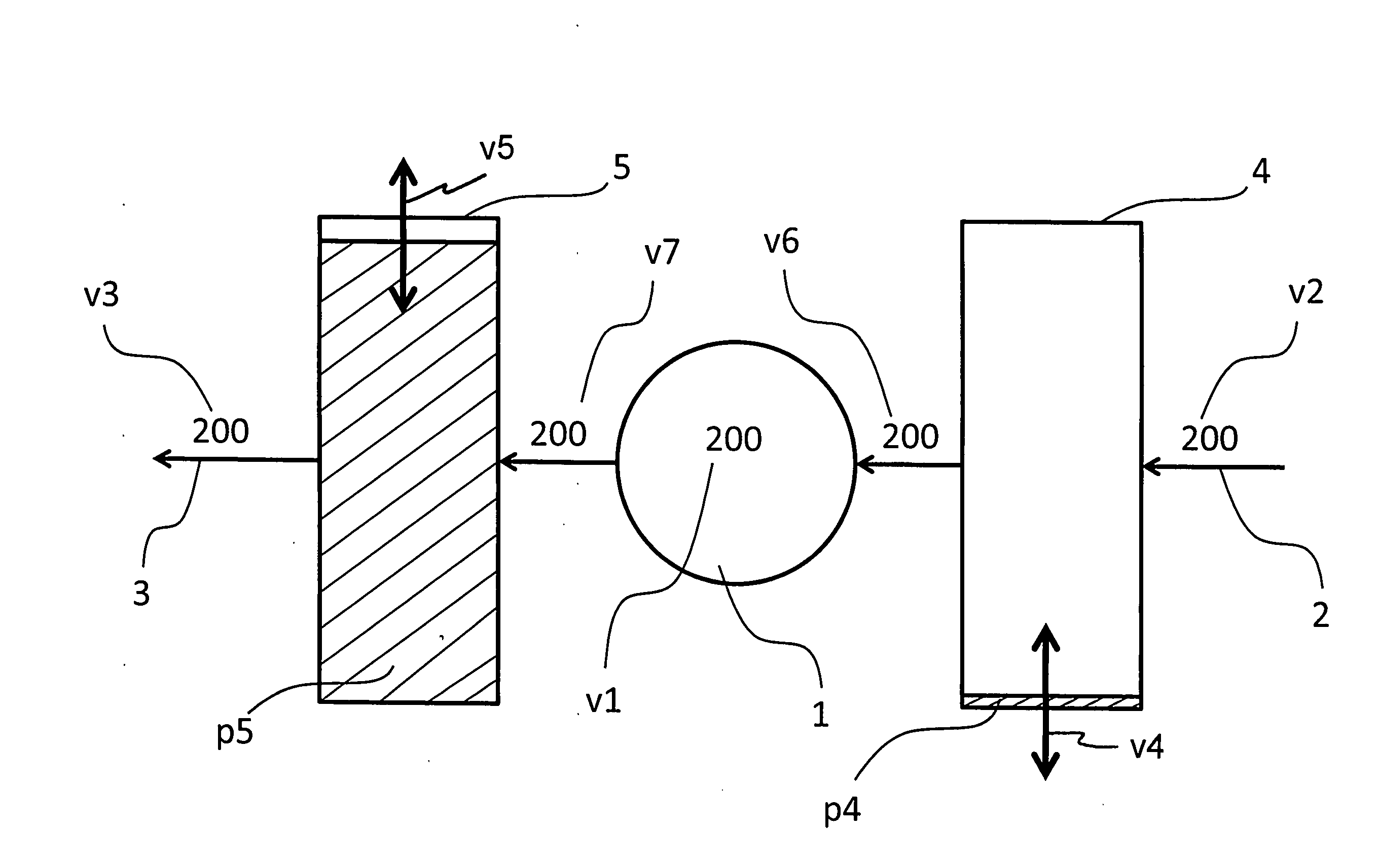
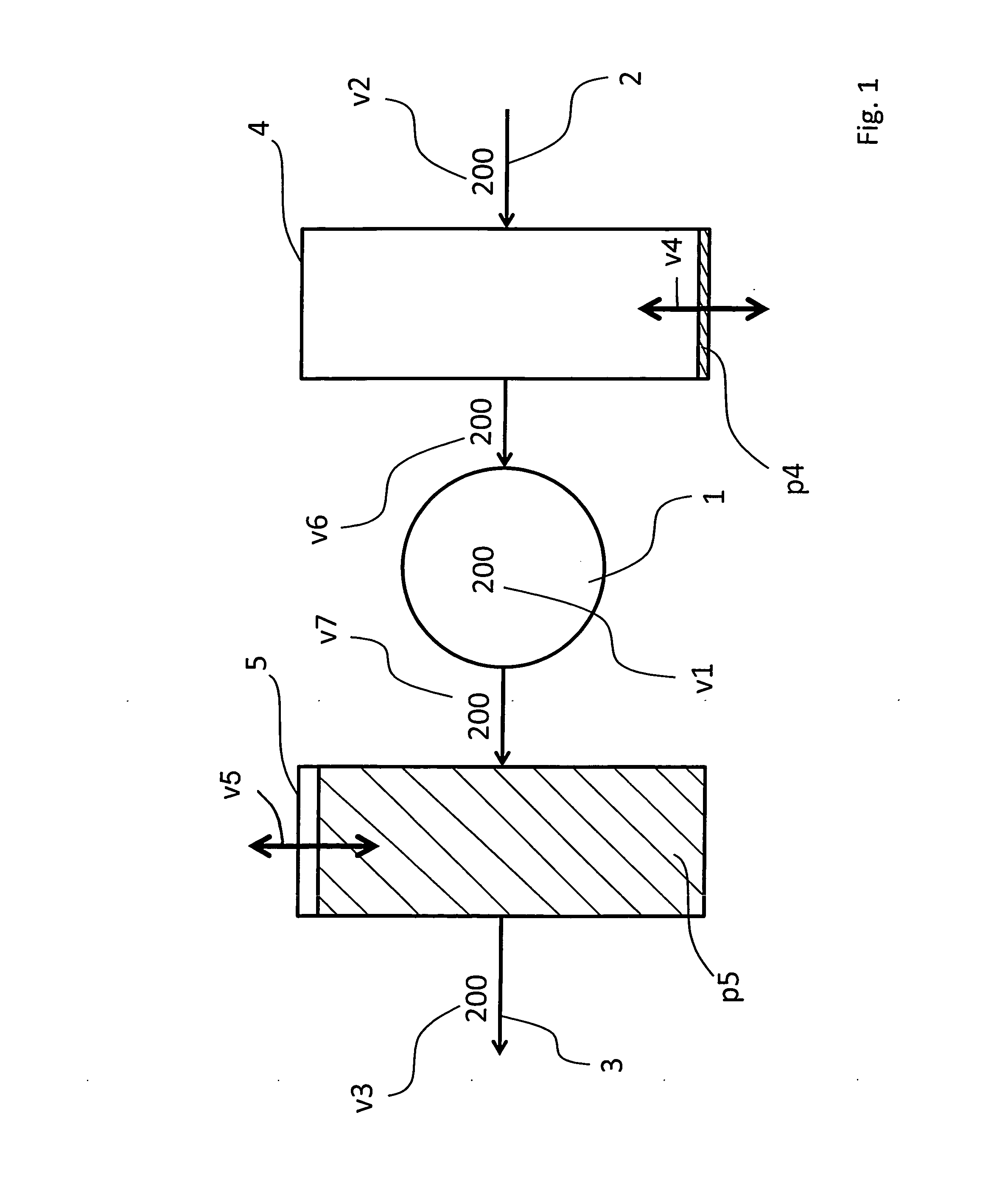
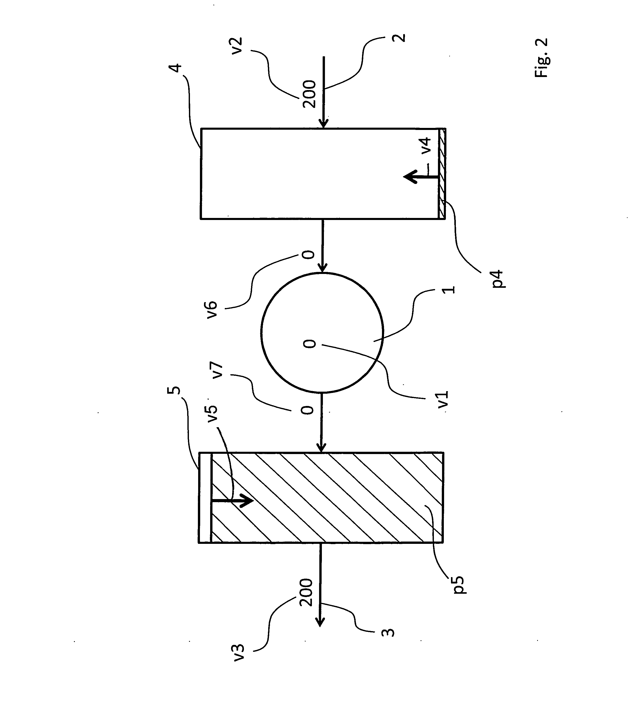
[0038]An assembly line 100 in FIGS. 1 through 8 includes a temporarily discontinuously operating processing station 1 with a production speed v1. The temporarily discontinuously operating processing station 1 has a production line section 2 connected upstream and a production line section 3 connected downstream. The production line section 2 operates with a production speed v2, the production line section 3 operates with a production speed v3.

[0039]Between the upstream production line section 2 and the temporarily discontinuously operating processing station 1, a first product buffer 4 with a buffer level p4 is arranged between the temporarily discontinuously operating processing station 1 and the downstream production line section 3 a second product buffer 5 with a buffer level p5 is arranged. A transfer of the products to be processed from the first product buffer 4 to the processing station 1 is provided with a transfer speed v6, a transfer of the process products from the proces...


PUM


Abstract

A production line with processing stations processing products with a production speed in products per unit time, the production line comprising a temporarily discontinuously operating processing station; a production line section connected upstream of the temporarily discontinuously operating processing station; a production line section connected downstream from the temporarily discontinuously operating processing station; a first product buffer arranged between the upstream production line section and the temporarily discontinuously operating processing station; and a second product buffer arranged between the temporarily discontinuously operating processing station and the downstream production line section.

Description

CROSS REFERENCE TO RELATED APPLICATIONS[0001]This application claims priority under 35 USC §119 to German Patent Application No. 10 2011 080 769.1 filed on Aug. 10, 2012, which application is hereby incorporated by reference.TECHNICAL FIELD[0002]The invention relates to a production line with processing stations which process products per unit time with a production speed, wherein the production line includes a processing station operating discontinuously from time to time, a production line section arranged upstream of the processing station and a production line section arranged downstream of the processing station.BACKGROUND OF THE INVENTION[0003]Production lines of the type recited supra are known in the art and are being used for example when producing and / or processing containers like aerosol cans, beverage cans or tubes.[0004]Typical production speeds of production lines of this type are between 50 and 2500 containers per minute (subsequently designated as cpm), wherein produ...

Claims


Application Information

Patent Timeline
Patent Type & Authority Applications(United States)
IPC IPC(8): B65B57/04
CPCB65B57/04B21D51/16G05B2219/32265G05B2219/31078G05B19/41865Y02P90/02
Inventor LINDEN, JOHANNESULLMANN, HERRN BERND
Owner MALL & HERLAND
Learn More