
Electronic device and temperature modulation method thereof

a technology which is applied in the field of electronic devices and temperature modulation methods of electronic devices, can solve the problems of crashing the computer, cpu temporary failure, and considerable heat generated by the central processing unit of the computer during high-speed operation, so as to improve the stability of the system and reduce the cost of operation

Inactive Publication Date: 2013-04-04
QUANTA COMPUTER INC
View PDF7 Cites 56 Cited by
  • Summary
  • Abstract
  • Description
  • Claims
  • Application Information

AI Technical Summary

Benefits of technology

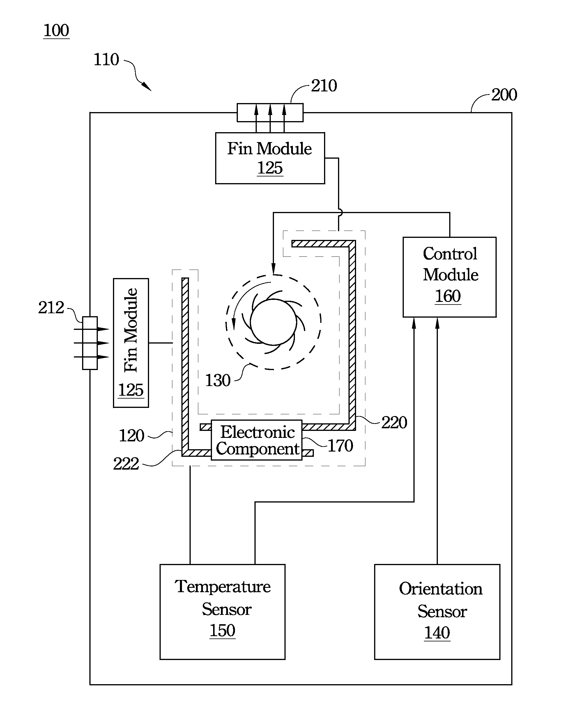
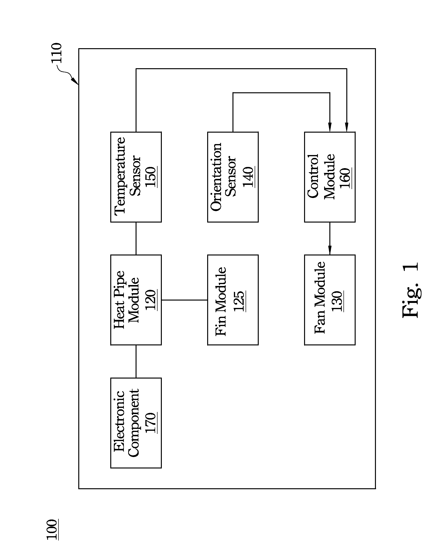
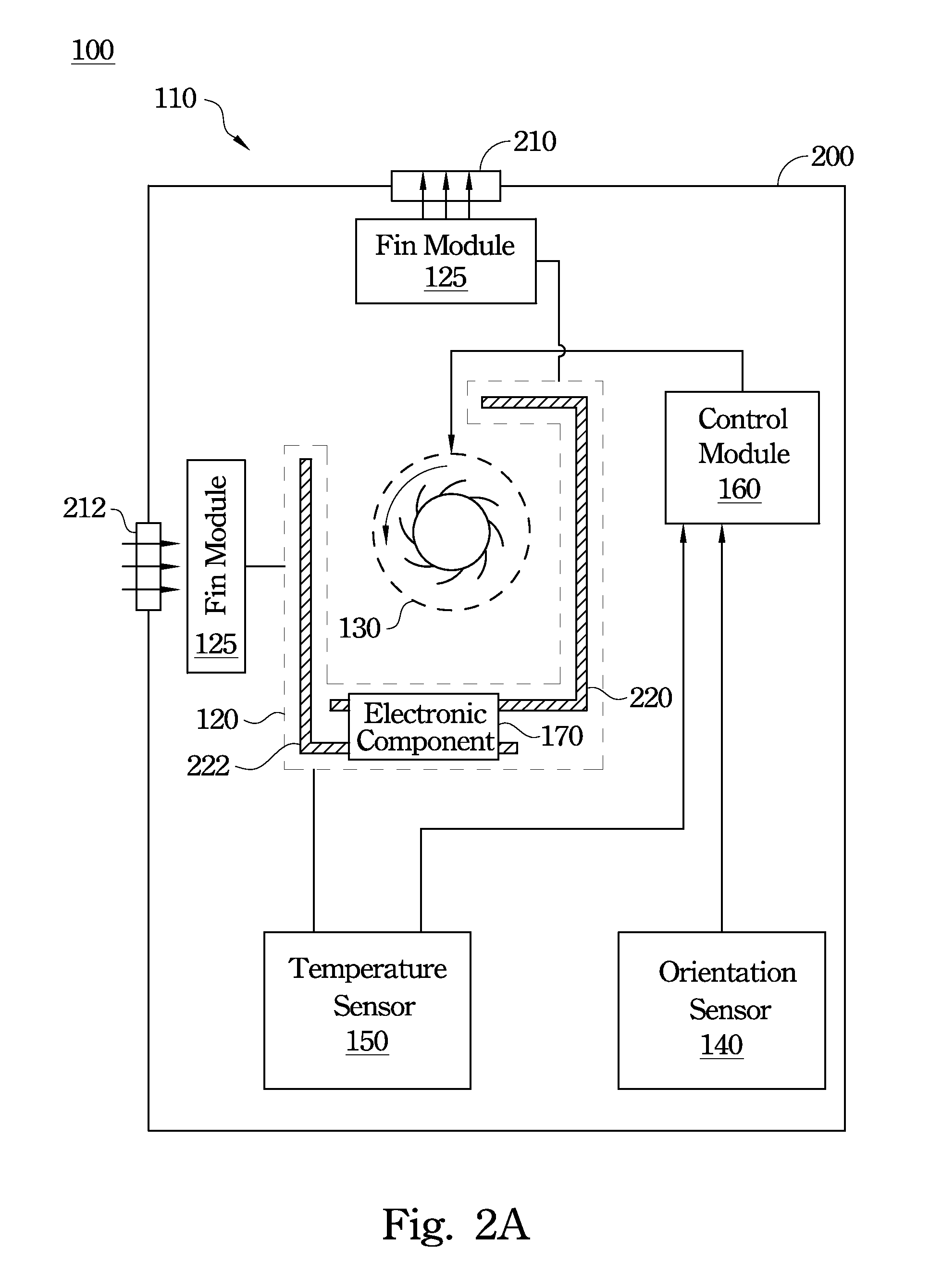
The present patent provides an electronic device and a method to prevent its heat dissipation performance from declining. It uses sensors to monitor the temperature of the device and the air flow through its openings. When the temperature is too high, a control module adjusts the rotational speed of the fans to improve heat dissipation. This results in better stability and performance of the device in different use conditions.

Problems solved by technology

For example, a central processing unit (CPU) for a computer generates considerable heat during high-speed operation.
When the temperature of the CPU exceeds a threshold temperature, this may possibly cause operation errors of the CPU or make the CPU temporary fail, and as a result crash the computer.
Moreover, when the temperature of the CPU far exceeds the threshold temperature, this may damage the transistors inside the CPU and thereby cause the CPU to permanently fail.
Performance degradation of the heat pipe may result due to a change in orientation.
When the heat pipe is disposed in a portable or a hand-held device, such as a notebook computer, a tablet computer, a smart mobile phone, etc., the performance degradation of the heat pipe is serious because the orientation of the portable or hand-held device may be changed to one that does not result in optimal operation of the heat pipe.

Method used


Image

  • Electronic device and temperature modulation method thereof
  • Electronic device and temperature modulation method thereof
  • Electronic device and temperature modulation method thereof

Examples


Embodiment Construction

[0031]In the following detailed description, for purposes of explanation, numerous specific details are set forth in order to attain a thorough understanding of the disclosed embodiments. It will be apparent, however, that one or more embodiments may be practiced without these specific details. In other instances, well-known structures and devices are schematically shown in order to simplify the drawing.

[0032]As used in the description herein and throughout the claims that follow, the meaning of “a,”“an,” and “the” includes reference to the plural unless the context clearly dictates otherwise. Also, as used in the description herein and throughout the claims that follow, the terms “comprise” or comprising,”“include” or “including,”“have” or “having,”“contain” or “containing” and the like are to be understood to be open-ended, i.e., to mean including but not limited to.

[0033]It will be understood that, although the terms first, second, etc. may be used herein to describe various elem...


PUM


Abstract

An electronic device and a temperature modulation method are disclosed herein. The electronic device includes a system body, a heat pipe module, a fan module, an orientation sensor, a temperature sensor and a control module. The system body includes an electronic component. The heat pipe module is connected to the electronic component. The fan module is installed in the system body. The orientation sensor can detect an orientation of the system body and output an orientation-sensing signal based on the orientation. The temperature sensor can detect a temperature of the heat pipe module and output a temperature-sensing signal based on the temperature. The control module can control rotation of the fan module according to at least one of the orientation-sensing signal and the temperature-sensing signal.

Description

RELATED APPLICATIONS[0001]This application claims priority to Taiwan Application Serial Number 100135548, filed Sep. 30, 2011, which is herein incorporated by reference.BACKGROUND[0002]1. Technical Field[0003]The present disclosure relates to electronic technology and an application of the same, and more particularly, an electronic device and a method of temperature modulation for the electronic device.[0004]2. Description of Related Art[0005]In recent years, with progress in computer science, the speed of computers has been continually increasing. To prevent electronic components inside a computer from overheating and temporarily or permanently failing, heat dissipation for electronic components inside the computer has become very important.[0006]For example, a central processing unit (CPU) for a computer generates considerable heat during high-speed operation. When the temperature of the CPU exceeds a threshold temperature, this may possibly cause operation errors of the CPU or ma...

Claims


Application Information

Patent Timeline
IPC IPC(8): F28F27/00
CPCG06F1/203G05D23/19
Inventor LIAO, WEI-CHENGCHANG, HSIAO-FANLIN, HUNG-MINGHSIEH, CHENG-WEN
Owner QUANTA COMPUTER INC
Learn More