
Autogenic reaction synthesis of photocatalysts for solar fuel generation

a photocatalytic and solar fuel technology, applied in the direction of metal/metal-oxide/metal-hydroxide catalysts, lanthanide oxides/hydroxides, bulk chemical production, etc., can solve the problems of high environmental cost of burning coal, high inefficiency of photocatalytic reduction of carbon dioxide, and inefficient conversion. remained a significant impedimen

Active Publication Date: 2013-03-28
UCHICAGO ARGONNE LLC
View PDF1 Cites 16 Cited by
  • Summary
  • Abstract
  • Description
  • Claims
  • Application Information

AI Technical Summary

Benefits of technology

The present invention provides a new method for producing photocatalytic materials that can efficiently convert solar energy into fuel and oxygen. These materials can be synthesized by heating precursor powders in a sealed reactor at high temperature and pressure. The resulting materials have a wide range of morphologies, particle shapes, and sizes, and can be used in flue gas or transportation exhaust to maintain carbon neutrality in the burning of fossil fuels. The materials can also be coated with other metals or promoters to enhance their performance. Overall, this invention provides a new way to produce highly effective photocatalysts for solar energy conversion.

Problems solved by technology

The environmental costs of burning coal, however, can be large.
Energy efficient capture and / or conversion of carbon dioxide is therefore an important technical challenge.
To date, the photocatalytic reduction of carbon dioxide is highly inefficient due to limitations in the solar spectrum absorption, electron-hole recombination events, and charge transfer of uncombined electron-hole pairs to adsorbed molecular species on the titanium oxide surface.
These approaches reportedly have increased the conversion efficiency to some degree; however, inefficient conversion has remained a significant impediment to widespread commercialization of this technology.

Method used


Image

  • Autogenic reaction synthesis of photocatalysts for solar fuel generation
  • Autogenic reaction synthesis of photocatalysts for solar fuel generation
  • Autogenic reaction synthesis of photocatalysts for solar fuel generation

Examples


example 1

TiO2 (Anatase) Before and After Removal of Carbon Coating

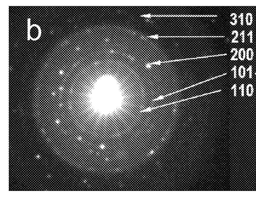
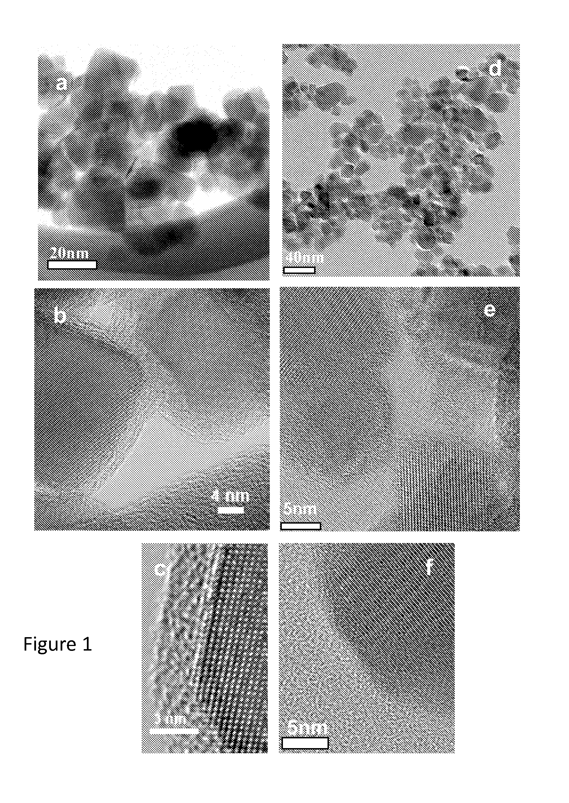
[0035]Carbon-encapsulated anatase TiO2 nanoparticles were prepared by thermolysis of a single precursor, titanium (IV) oxyacetyl acetonate (TiO[C5H8O2]2), in a sealed reactor (Haynes 230 alloy, 10 mL capacity) fitted with a pressure gauge. Two grams of the precursor material were placed in the reactor under a nitrogen atmosphere. After being tightly sealed, the reactor was placed in a furnace and heated to 700° C. at a heating rate of 30° C. / minute. The temperature of the reactor was held at 700° C. for 1 hour, during which a maximum autogenic pressure of 150 psi (10.2 atm) was reached. Thereafter, the reactor was cooled gradually to room temperature, and the remaining pressure was released before it was opened to collect the product (a black powder). A thermogravimetric analysis (TGA, Seiko Exstar 6000) of the resulting black powder revealed that the as-prepared TiO2 product contained approximately 30% carbon by weight (i.e.,...

example 2

Composition and Structure of Anatase TiO2 Photocatalyst

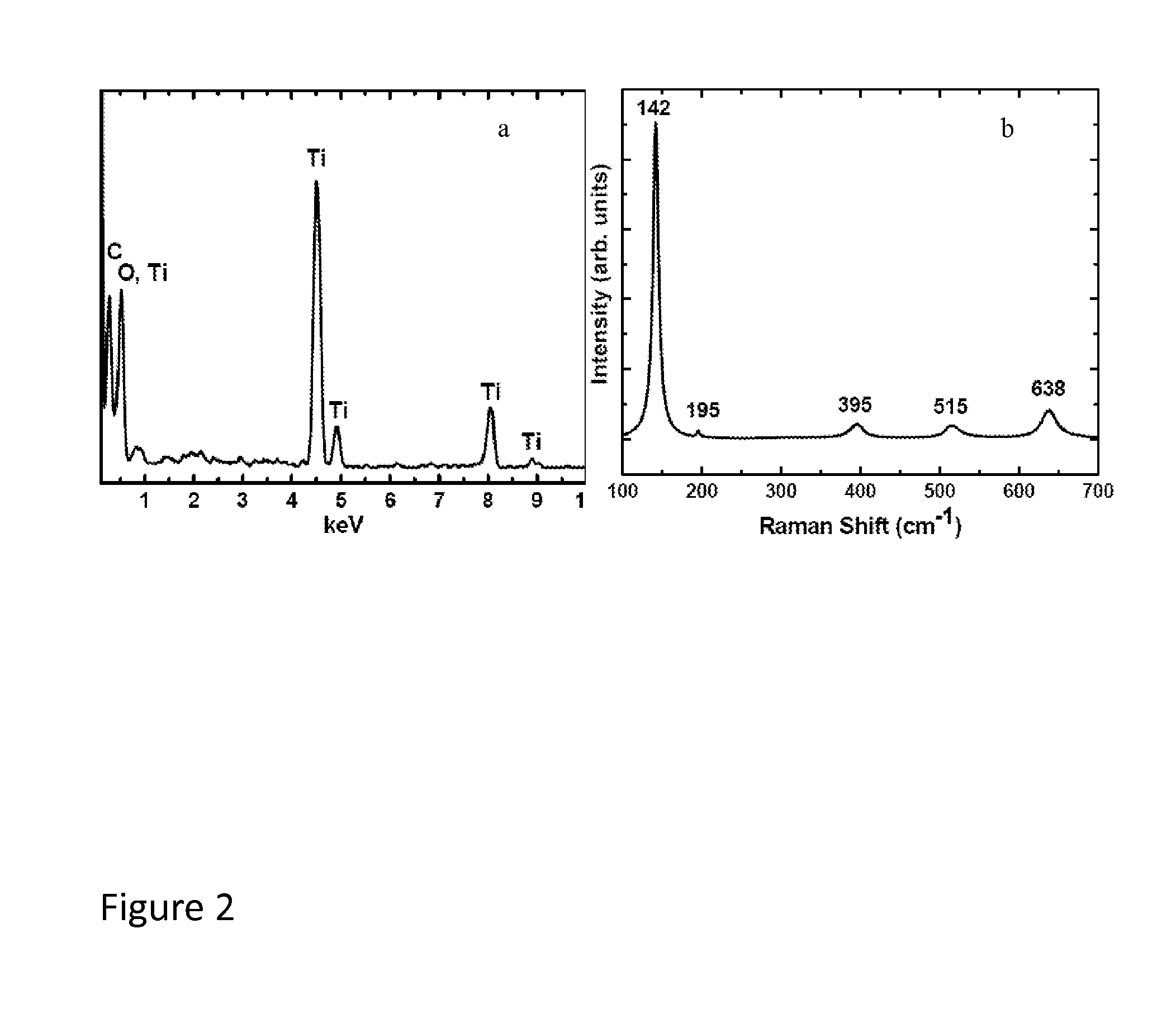
[0038]An elemental analysis of the substantially carbon-free TiO2 nanoparticle material of Example 1, obtained by energy dispersive x-ray spectroscopy (EDS), showed only C, O, and Ti, confirming the purity of the TiO2 produced as described herein. The small presence of carbon (inset in FIG. 2a) is primarily due to the supported sample grid. A Raman spectrum of the TiO2 same product, exhibited the strongest band at 142 cm−1 and additional bands at 195, 395, 515, and 638 cm−1, which is characteristic of pure anatase TiO2. It has been reported that the phase transformation of pure anatase to rutile occurs at around 600° C. Thus, the Raman data demonstrate that the TiO2 particles formed under the autogenic reaction conditions described herein surprisingly remained in the anatase phase even though the reaction temperature (about 700° C.) was about 100 degrees higher than the reported phase transition temperature for conversion of ana...

example 3

SnO2 Nanoparticles: Before and After Removal of Carbon Coating

[0039]Carbon-coated SnO2 nanoparticles were prepared by thermolysis of a single precursor, tin ethoxide, Sn(OC2H5)2, in a the same autogenic reactor setup used in Example 1. After being tightly sealed, the pressure gauge of the reactor was attached and the reactor was placed in a furnace to heat up to about 600° C. with a heating rate of about 20° C. / minute. The temperature of the reactor was held at 600° C. for 1 hour, during which time a maximum autogenic pressure of about 100 psi was reached. Thereafter, the reactor was cooled gradually to room temperature (over about 4 hours), and the remaining pressure was released before the reactor was opened to afford carbon-coated SnO2 nanoparticles (SnO2—C) as a black powder. A sample of the carbon-coated material was heated in air at about 450° C. to remove the carbon coating as in Example 1.

[0040]The particle diameters and structure of the SnO2—C and SnO2 particles were studie...


PUM

PropertyMeasurementUnit
temperatureaaaaaaaaaa
particle sizeaaaaaaaaaa

Abstract

In one preferred embodiment, a photocatalyst for conversion of carbon dioxide and water to a hydrocarbon and oxygen comprises at least one nanoparticulate metal or metal oxide material that is substantially free of a carbon coating, prepared by heating a metal-containing precursor compound in a sealed reactor under a pressure autogenically generated by dissociation of the precursor material in the sealed reactor at a temperature of at least about 600° C. to form a nanoparticulate carbon-coated metal or metal oxide material, and subsequently substantially removing the carbon coating. The precursor material comprises a solid, solvent-free salt comprising a metal ion and at least one thermally decomposable carbon- and oxygen-containing counter-ion, and the metal of the salt is selected from the group consisting of Mn, Ti, Sn, V, Fe, Zn, Zr, Mo, Nb, W, Eu, La, Ce, In, and Si.

Description

CONTRACTUAL ORIGIN OF THE INVENTION[0001]The United States Government has rights in this invention pursuant to Contract No. DE-AC02-06CH11357 between the United States Government and UChicago Argonne, LLC representing Argonne National Laboratory.FIELD OF THE INVENTION[0002]This invention relates to the energy efficient photocatalytic conversion of carbon dioxide gas and water vapor to methane and other hydrocarbon fuels, particularly promoted by sunlight (referred to herein as “solar-derived fuel” or “solar fuel”). In particular, the invention relates to wide band-gap photocatalytic materials, as well as the synthesis and surface modification thereof, as materials for promoting solar fuel production.BACKGROUND OF THE INVENTION[0003]As developing countries begin to prosper, fossil fuels will continue to be the primary source of the world's energy. Large deposits of coal throughout the world and the United States are relatively inexpensive and geopolitically stable. The environmental ...

Claims


Application Information

Patent Timeline
Patent Type & Authority Applications(United States)
IPC IPC(8): C07C1/20C01G19/02C01F17/00C01G49/08B01J21/06C01G23/047C01G25/02B82Y30/00C01F17/235
CPCC01G19/02C07C2523/745B82Y30/00C07C1/12C07C2521/06C07C2523/14C01P2002/54C01P2002/72C01P2002/82C01P2002/85C01P2004/04C01P2004/64C01P2006/80C01F17/0043C01G23/047C07C2523/10B01J37/08B01J37/084B01J37/14B01J21/063B01J23/06B01J23/10B01J23/14B01J23/745B01J35/0013B01J35/004C07C2523/06C07C9/04C01F17/235B01J35/23B01J35/39Y02P20/52
Inventor INGRAM, BRIAN J.POL, VILAS G.CRONAUER, DONALD C.RAMANATHAN, MURUGANATHAN
Owner UCHICAGO ARGONNE LLC
Learn More