
Structural Strapped Multi-Pack Packaging

a multi-pack and strapped technology, applied in the direction of packaging, containers with multiple articles, containers, etc., can solve the problems of damage to the integrity of the whole pallet load, the current packaging practice does not follow structural engineering principles, and the intrinsic strength of the containers forming the package contents is not fully utilized, so as to reduce the content of packaging materials

Inactive Publication Date: 2013-03-21
MIKRALJO
View PDF8 Cites 9 Cited by
  • Summary
  • Abstract
  • Description
  • Claims
  • Application Information

AI Technical Summary

Benefits of technology

The present invention provides a package assembly with significantly less packaging material. The package is made by combining the structure of the good containers in the package with the package itself using inelastic tensioned binding members to compress the package and its contents into an integrated, stable, and load-bearing unit. This reduces the amount of material used in the package and makes it easier to transport and handle.

Problems solved by technology

Current packaging practice does not follow structural engineering principles of integrating all the elements of a package contents with those of the packaging, per se.
Thus the available intrinsic strengths of the containers forming the package contents are not fully utilized with that of the package elements per se to provide a robust integrated load-bearing package unit.
This failure to optimize package strength is then reflected in potential failure of individual packages in a multi-tiered palletized or transported load, with consequent damage to the integrity of the whole pallet load, under the stresses resulting from the static and dynamic forces of transportation.
The current modes of packaging frequently permit relative movement and fretting between adjacent containers within a package, which translates, under transportation conditions, into goods and / or containers damaged from mutual impact with containers within the package.
Such internal movement of containers within a package can include sliding, pivoting and tilting, and can result in skewing of containers within the package, which renders the package unstable, thus destroying the stability and integrity of the pallet load, with a consequent cascade of further damage to adjoining packages and their contents.
The prior use of strapping has been generally ineffective, and raises problems of pallet-load-bearing stability, having been used primarily in a bundling role, with a failure to recognize the strap's potential contribution in an integrated load bearing structural component.
Earlier theoretical packaging work resulted in undependable packages in the load-bearing sense with un-predicted failures.
These shortcomings have been and are particularly disadvantageous in the supply / distribution service, where the primary focus is on palletized handling and transportation of packages of wares.
Consequently, commercial application of any similar horizontal tensioned strapped package constructs in the supply chain has not been previously achieved.
Strapped packages having rows and / or columns of three or more containers, upon the application of the forces of transportation, face an additional problem.
This shifting causes the containers to become loose in the strapped package, and to possibly rotate or skew in the package, such that the package and containers lose their ability to withstand the application of vertical, horizontal or other transportation forces resulting from the dynamic forces applied to the package during transportation, such as impact forces, shear forces and rotary forces.

Method used


Image

  • Structural Strapped Multi-Pack Packaging
  • Structural Strapped Multi-Pack Packaging
  • Structural Strapped Multi-Pack Packaging

Examples


embodiment 66

[0062]In FIG. 5 a modified divider embodiment 66 has end flaps 68 and 70 for gluing attachment to the adjoining wall portion (not shown) of the package 52 of FIG. 3. The outer or x′d surfaces 72 are the gluing surfaces.

embodiment 74

[0063]In FIG. 6 the modified divider embodiment 74 has projecting insert tab ends 76 which are inserted into recesses 78 that are die-cut into the surfaces of package 52. It will be understood that these attachment modes may be applied to other separators and dividers of the present invention, and that other attachment modes are as known in the art may be used.

[0064]Referring to FIG. 7, a package 80 is shown, having larger containers 82 interspaced with secondary smaller containers 84, referred to above as possibly being tequila bottles 82, interspaced by smaller bottles of margarita mix 84. The containers 82, 84 of different sizes are positioned in the package 80 with the pluralities of one size containers 82 interposed between containers of a second size 84. When a tensioned strap (not shown in FIG. 7) is applied laterally to package 80, the adjacent containers of different sizes are compressed into mutual immobilizing positions in the wrapper 86, thus forming a stable load-bearin...


PUM

PropertyMeasurementUnit
massaaaaaaaaaa
frictional forceaaaaaaaaaa
frictional forcesaaaaaaaaaa

Abstract

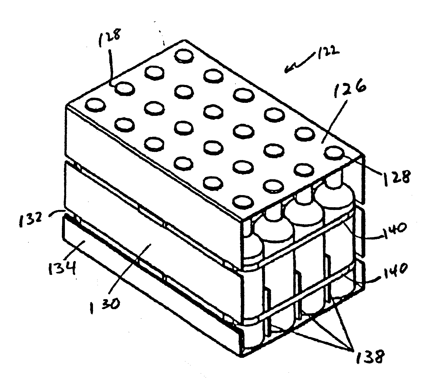
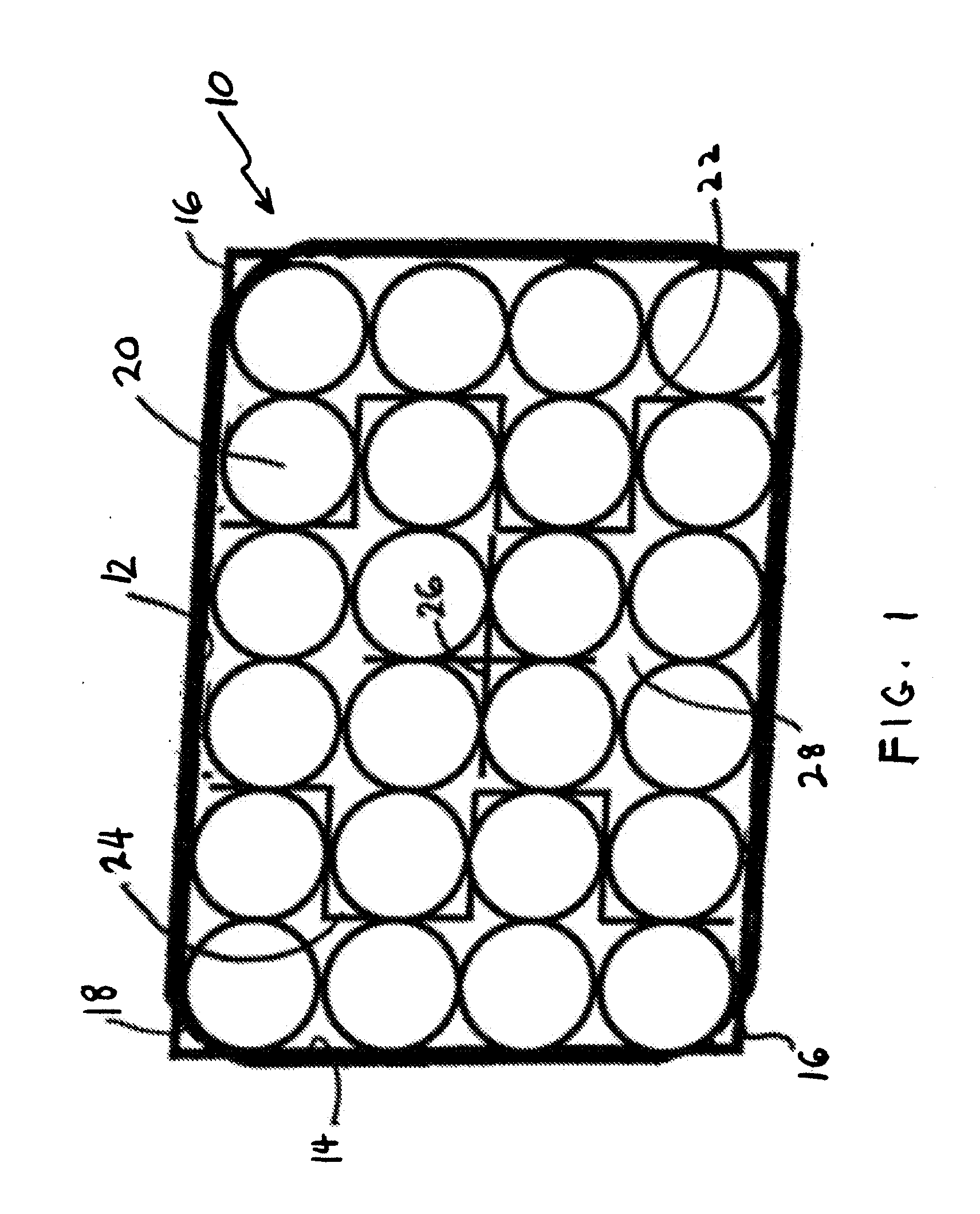
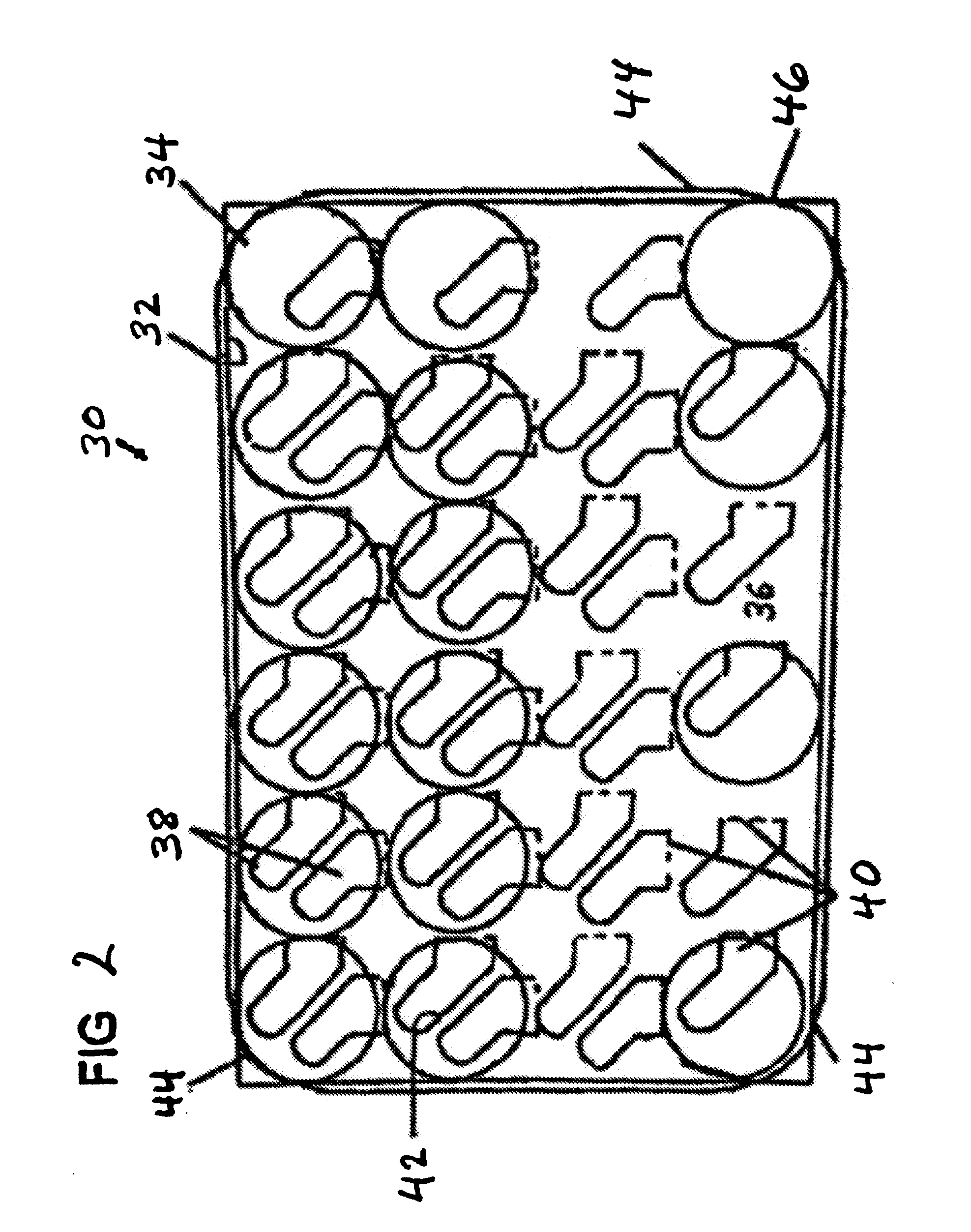
A composite unitary package for transporting goods in containers includes a wrapper assembly having two side portions extending vertically from a bottom portion and around the outside of a plurality of the containers. Spacers partially or fully extend between certain of the containers, and one or more inelastic tensioned straps extends around the side portions of the wrapper assembly, and compressively binds the side wrapper assembly portions, the spacers and the containers together such that the frictional forces on the combination of wrapper assembly, spacers and containers form a stable, load-bearing package that withstands transportation forces.

Description

[0001]This application is a continuation-in-part of U.S. patent application Ser. No. 11 / 594,187, filed Nov. 8, 2006 which is a continuation-in-part of U.S. patent application Ser. No. 11 / 082,984, filed Mar. 18, 2005.BACKGROUND[0002]This invention is directed to strap-reinforced compressed packaging, including paperboard packaging with separation of wares in the packaging, and the integration of the container in the package. Separation spacers, a tensioned strap, and portions of the package wrapper form a tightly-held load-bearing structural unit suited to multi-layer palletizing, the rigors of transportation, storage and shelf display purposes, with significant economic and ecological benefits.[0003]Paperboard packaging is extensively used for the transportation and display of goods. Current packaging practice does not follow structural engineering principles of integrating all the elements of a package contents with those of the packaging, per se. Thus the available intrinsic stren...

Claims


Application Information

Patent Timeline
Patent Type & Authority Applications(United States)
IPC IPC(8): B65D65/02
CPCB65D65/02B65D2571/00141B65D2571/00265B65D2571/0029B65D2571/0066B65D2571/0082B65D2571/00716B65D2571/00987B65D71/18B65D2571/00216B65D2571/00401B65D2571/00666
Inventor DILLON, RALPH L.NOFERI, JOSEPH F.
Owner MIKRALJO
Learn More