Directional valve and breathing mask with a directional valve

a directional valve and breathing mask technology, applied in breathing masks, breathing protection, life-saving devices, etc., can solve the problems of relatively high flow resistance, failure to complete closing operation, and high leakage value, so as to improve the directional valve. , the effect of high moisture conten

Active Publication Date: 2013-03-21
DRAGER SAFETY
View PDF4 Cites 3 Cited by
  • Summary
  • Abstract
  • Description
  • Claims
  • Application Information

AI Technical Summary

Benefits of technology

The patent text describes a new way to fix a valve membrane in a valve housing. By fixing the membrane in a slightly eccentric position, the flow resistance is reduced compared to a centrally fixed membrane. This results in a 60% reduction in flow resistance at gas flows of up to 80 L / minute. The valve membrane can have a circular, oval, square, or rectangular shape, and it is fixed by a Y-shaped fixing lug at the valve seat. The fixing lug is designed to ensure a secure seal without any adhesive effects caused by condensed moisture. The entire opening within the sealing surface is available for the flow of gas, and both a mechanically stable fastening of the valve membrane and reduced flow resistance are achieved with the eccentric fixation of the membrane.

Problems solved by technology

The drawback of the prior-art valve construction is that the flow resistance is relatively high.
Even though a markedly lower flow resistance can be obtained with this valve construction compared to a directional valve with centrally fastened valve membrane, the leakage values are nevertheless higher because the valve membrane is fastened on one side, and the valve membrane may remain stuck to the inside of the valve bonnet due to adhesive forces in case of a possible condensation of moist expired air, as a result of which the closing operation of the directional valve may be delayed or the closing operation may fail to occur altogether.

Method used


Image

  • Directional valve and breathing mask with a directional valve
  • Directional valve and breathing mask with a directional valve
  • Directional valve and breathing mask with a directional valve

Examples


Embodiment Construction

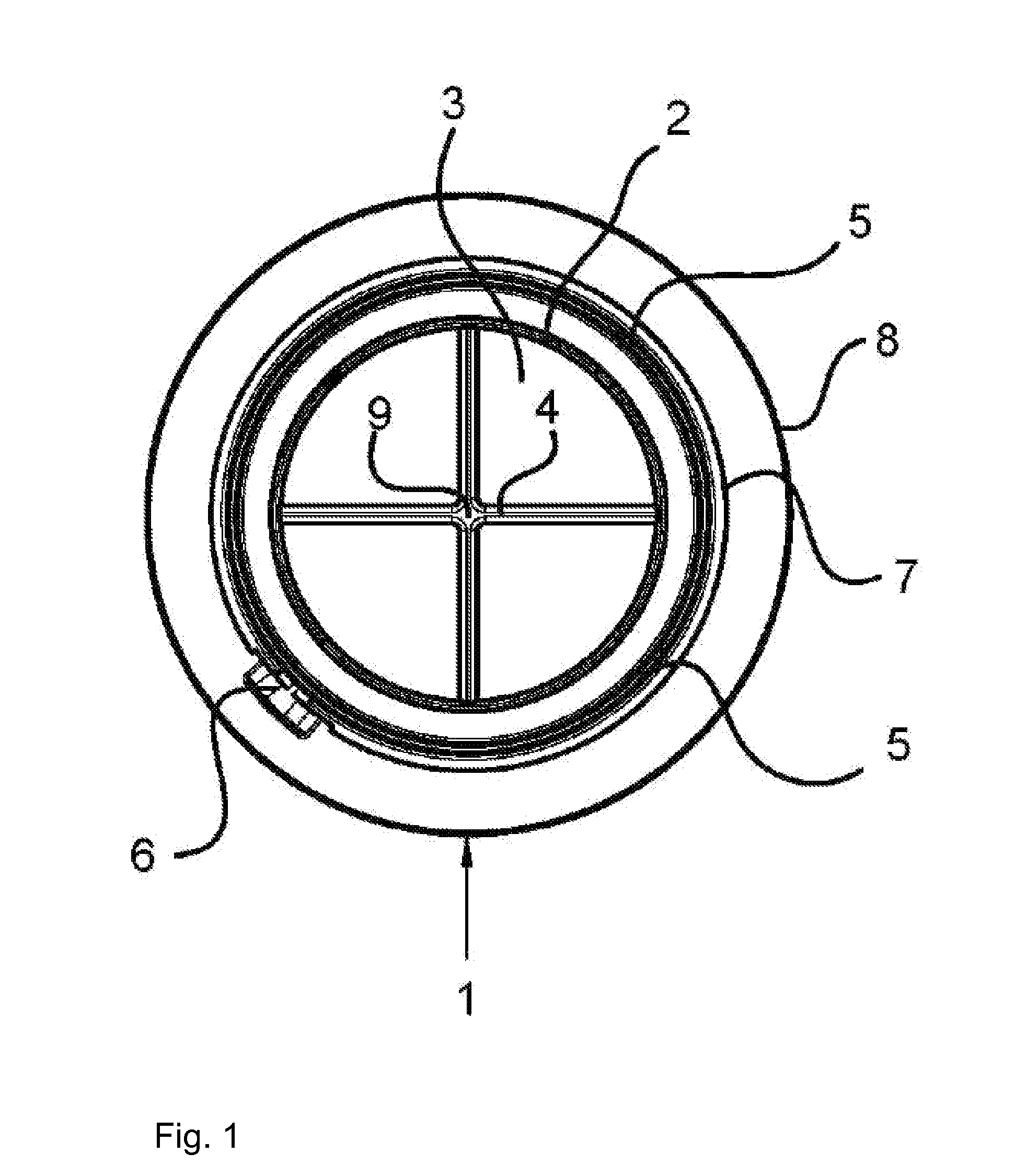
[0013]Referring to the drawings in particular, FIG. 1 shows a valve seat with a flat sealing surface 2, which surrounds an opening 3 through which the gas flows. Opening 3 is divided by a valve cross 4 into four sectors. An upright edge 5, which receives a valve membrane, not shown in FIG. 1, and centers same against the sealing surface 2, is located around valve surface 2. A centering projection 6 and a circumferential bead 7 are located on the outside of edge 5. The underside 8 of valve seat 1 is connected to a filter mask, not shown in the figure. The webs of valve cross 4 intersect in a center 9.

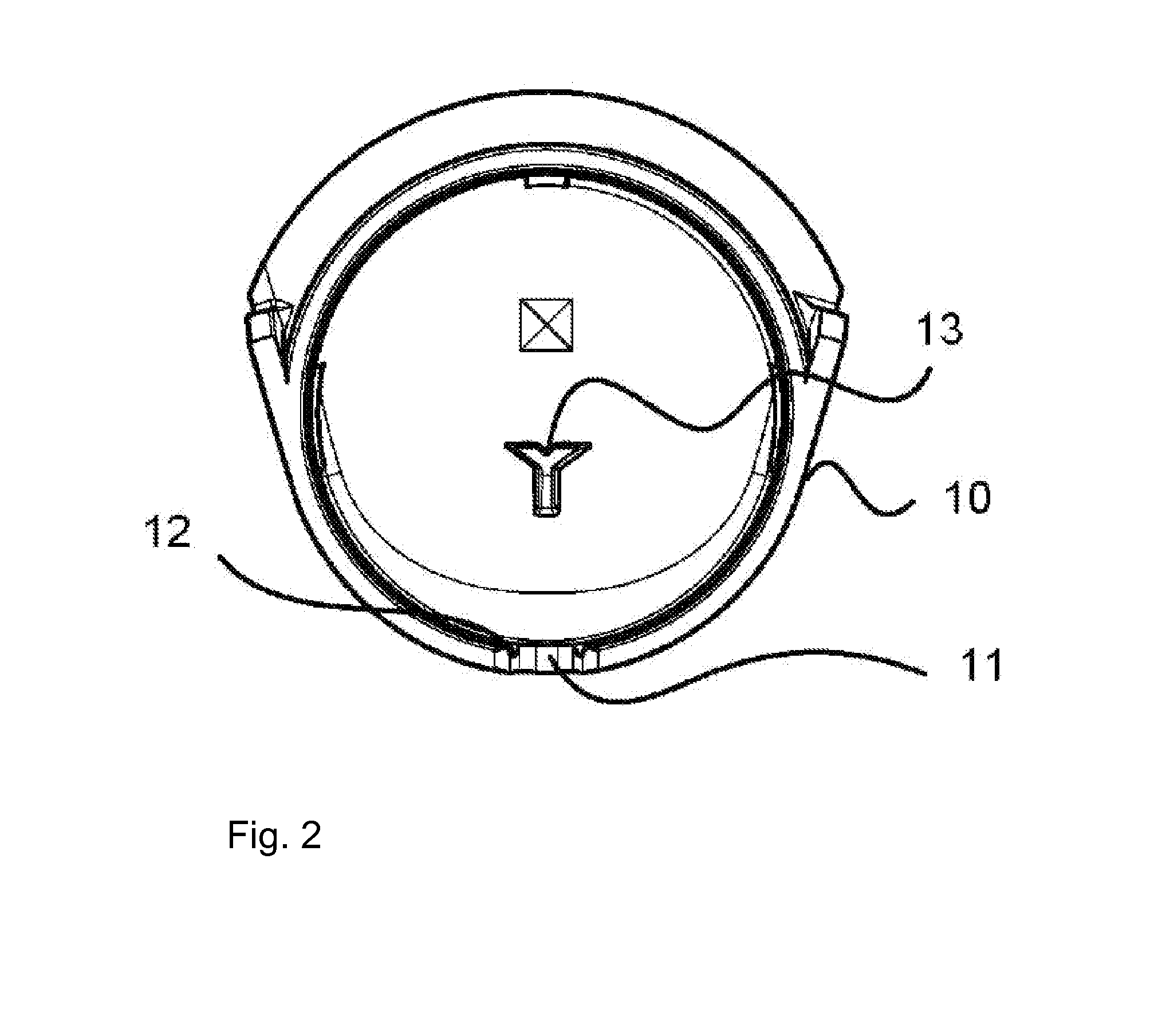
[0014]FIG. 2 illustrates a valve bonnet 10, which is placed on the valve seat 1, FIG. 1, and has for this a centering groove 11, corresponding to centering projection 6, and a circumferential groove 12, corresponding to bead 7. On the inside, valve bonnet 10 has a fixing lug 13, which is directed towards the sealing surface 2.

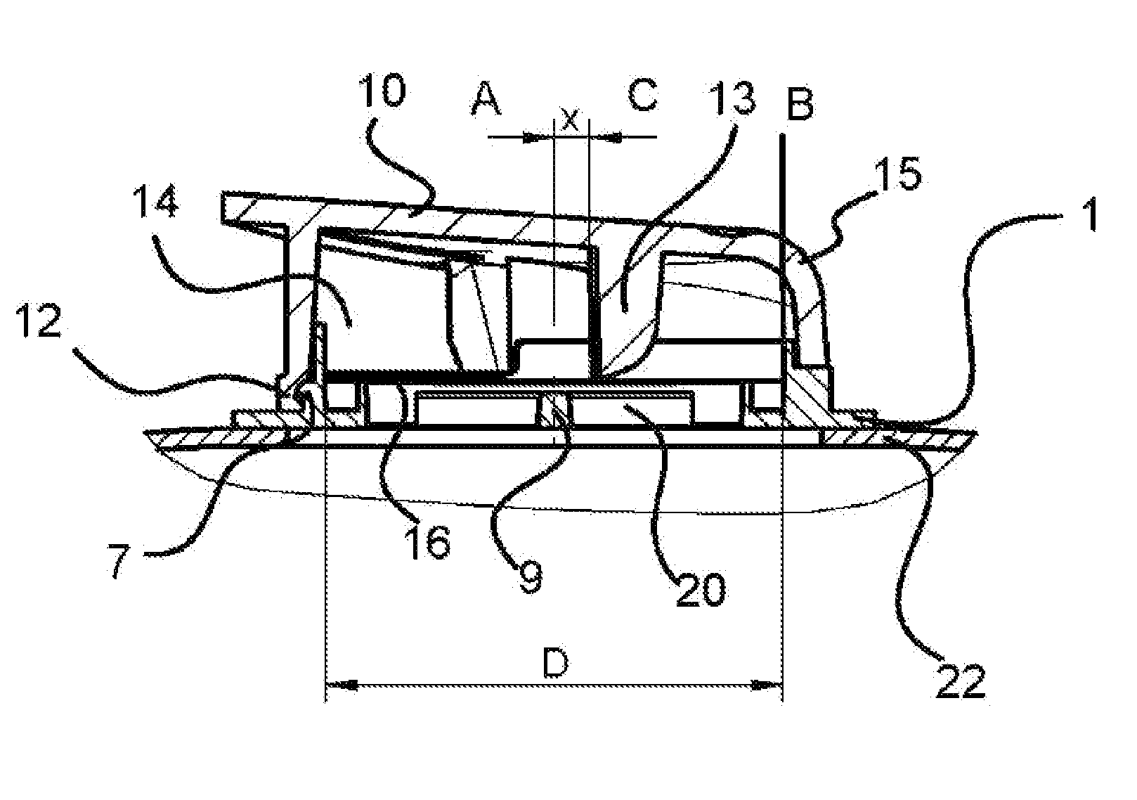
[0015]Valve seat 1 and valve bonnet 10 together form a valve h...


PUM


Abstract

A directional valve includes a fixing lug (13), which is arranged eccentrically to a valve membrane (16) and is arranged at a valve housing (15). The dimensions of the fixing lug (13) are selected for fixing the valve membrane (16) relative to the sealing surface (2) of valve seat (1). The size of the eccentric offset (x) is in a range between 8% and 15% of the axis length (D) of the greatest longitudinal extension of valve membrane (16).

Description

CROSS REFERENCE TO RELATED APPLICATIONS[0001]This application claims the benefit of priority under 35 U.S.C. §119 of German Patent Application DE 10 2011 113 716.9 filed Sep. 17, 2011, the entire contents of which are incorporated herein by reference.FIELD OF THE INVENTION[0002]The present invention pertains to a directional valve and to a breathing mask with a directional valve.BACKGROUND OF THE INVENTION[0003]A breathing mask with port openings for filters as well as with an inspiration valve and with an expiration valve is known from DE 40 17 336 C1. Respirator filters can be arranged at various points of the half mask by means of a connection adapter, which can be fastened to a half mask in two preferential positions. The gas flow is sent to the mask user via the respirator filters into the mask interior by means of directional valves, which are arranged both in the area of the respirator filters and at the gas outlet of the breathing mask, and the breathing gas enters the envir...

Claims


Application Information

Patent Timeline
Patent Type & Authority Applications(United States)
IPC IPC(8): A62B18/10
CPCA62B18/10
Inventor ROSERT, MICHAELLESKE, DENNISHEYER, HARALDPANCUR, THOMAS
Owner DRAGER SAFETY
Why Eureka
Try Eureka