
Form fill compression seal and cut-off packaging system for compressible goods

a packaging system and form fill technology, applied in the field of form fill compression seal and cut-off packaging system for compressible goods, can solve the problems of more difficult accurate control of bags, and achieve the effects of improving the form fill compress and seal technology, improving manufacturing speed, and accurate bag handling

Inactive Publication Date: 2013-03-21
ILLINOIS TOOL WORKS INC
View PDF4 Cites 9 Cited by
  • Summary
  • Abstract
  • Description
  • Claims
  • Application Information

AI Technical Summary

Benefits of technology

The present disclosure aims to improve the form fill compress and seal technology by using wicketed open-bottom vacuum bags or chain-linked open-bottom vacuum bags, which may have zippered closures or one-way vacuum valves. The bags are made from two-layer laminate films and have pre-punched apertures spaced across the open bottom. Using drive machinery with sprocket pins which align with the pre-punched apertures, very accurate registration of the bags is achieved along with increased manufacturing speeds. The configuration allows for fast and simple changeover from packing of one size of compressible goods to another size of compressible goods. The process is simplified because the control, fixed or datum side becomes the inverted closed top of the bags, which may include a zipper. The incoming film can be a continuous piece of material across its width, and there may be only one throw-away piece, rather than two pieces. The apertures, can be pre-punched during the bag making process or even punched in the packaging machinery. The process can run at a speed convenient to the operator, the machine can be easier to control and may even have a smaller footprint as compared to previous designs.

Problems solved by technology

This requires that the side of the bag with the loop or thickened material must be the control fixed or datum side, which may make the bags more difficult to control accurately.

Method used


Image

  • Form fill compression seal and cut-off packaging system for compressible goods
  • Form fill compression seal and cut-off packaging system for compressible goods
  • Form fill compression seal and cut-off packaging system for compressible goods

Examples


Embodiment Construction

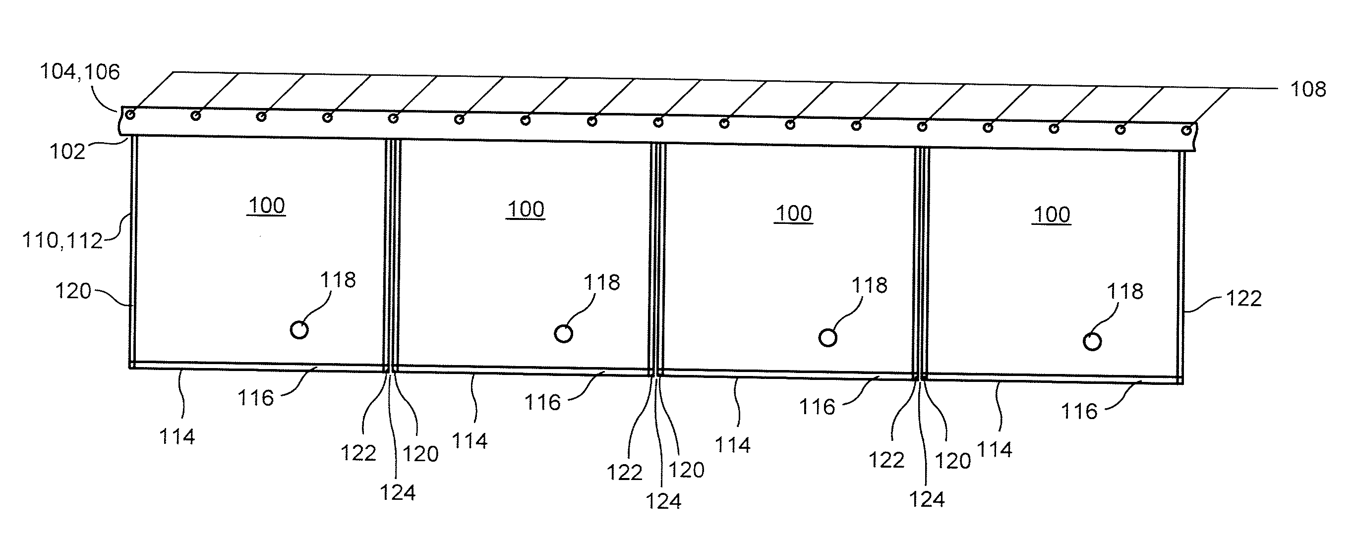
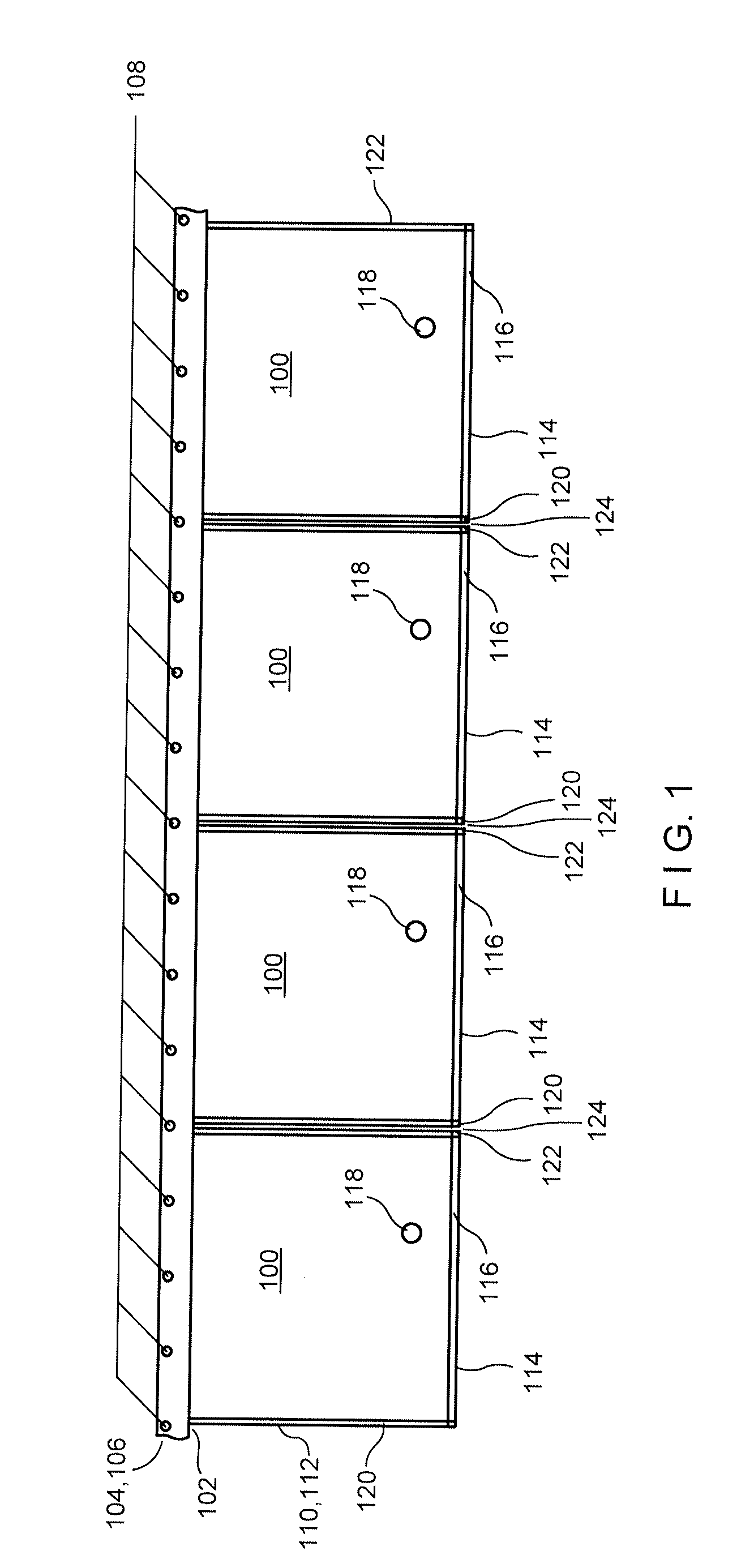
[0022]Referring now to the drawings in detail wherein like numerals indicate like elements throughout the several views, one sees that FIG. 1 is a side plan view of a concatenation of chain-linked bags 100 as used in embodiments of the present disclosure. The bags 100 are inverted so that open bottom 102 is presented as the uppermost part of the bag 100 in the orientation of FIG. 1. The open bottom 102 is formed between offset flanges 104, 106 (see FIG. 3) thereby presenting a path for filling or loading. Typically, one flange, illustrated here as flange 104 includes a series of spaced alignment apertures 108. The spacing of the apertures 108 corresponds to the spacing of the sprocket pin drive elements of the manufacturing apparatus (see subsequent figures). Front and rear polymeric walls 110, 112 extend from the flanges 104, 106 to form the bags 100, which a storage space formed therebetween. The top 114 of the bags 100, configured at the lowermost portion of the bags in the illus...


PUM


Abstract

The present disclosure relates to a packaging system for compressible goods utilizing pre-punched alignment apertures on wicketed and / or chain-linked open bottom bags. The disclosure relates to a bag transport and indexing system through the form fill compress and seal system. The disclosure further relates to the use of sprocket pins spaced accordingly on either a horizontal linear or rotary machine so that the sprockets correspond to the pre-punched apertures on the wicketed and / or chain-linked open bottom bags.

Description

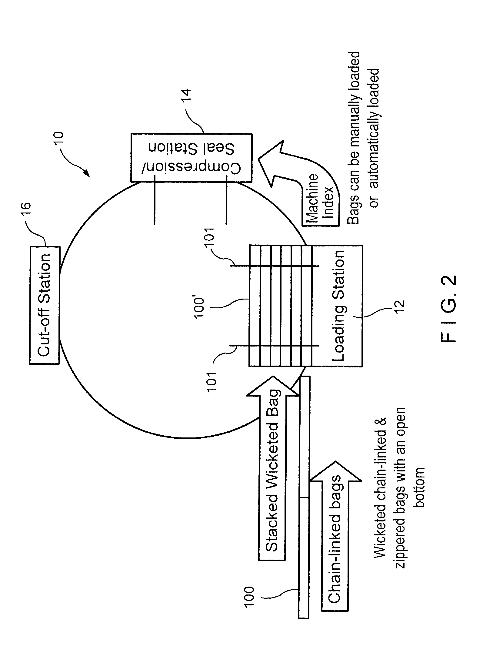
[0001]This application claims priority under 35 U.S.C. §119(e) of U.S. provisional patent application Ser. No. 61 / 536,263 filed on Sep. 19, 2011, the contents of which is hereby incorporated by reference in their entirety.BACKGROUND OF THE DISCLOSURE[0002]1. Field of the Disclosure[0003]The present disclosure relates to a packaging system for compressible goods utilizing pre-punched alignment apertures on wicketed and / or chain-linked open bottom bags. The disclosure relates to a bag transport and indexing system through the form fill compress and seal system.[0004]2. Description of the Prior Art[0005]In the prior art, the form fill compress and seal technology has been substantially developed. This technology forms a container, typically from polymeric material, fills the container with a compressible good, typically a large compressible good such as, but not limited to, a blanket or similar item, compresses the compressible good within the package and then seals the package shut.[0...

Claims


Application Information

Patent Timeline
IPC IPC(8): B65B31/00
CPCB65B31/00B65B43/123B65B51/146B65B5/045B65B31/047B65B43/267B65B61/188B31B2219/924B31B70/946
Inventor MCDONALD, DANIELCREVIER, DONALD LEESHARE, LAWRENCEPIOTROWSKI, STANLEYGONZALEZ, BENITOLIND, GARY
Owner ILLINOIS TOOL WORKS INC
Learn More