
Electrical device power management

a technology for electric devices and power management, applied in the direction of cell components, primary cell maintenance/service, instruments, etc., can solve the problems of battery depletion, power supply failure during use, and not being apparent if a battery has been used befor

Active Publication Date: 2013-03-14
COVIDIEN AG
View PDF1 Cites 19 Cited by
  • Summary
  • Abstract
  • Description
  • Claims
  • Application Information

AI Technical Summary

Benefits of technology

The patent text discusses a feature of an electrical device that allows it to use different batteries of varying capacity while ensuring that it operates safely and efficiently throughout the procedure. This feature reduces the risk of failure in devices that use batteries with different compositions and capacities. Additionally, the text mentions that the electrical device may have a recess on its surface to improve grip for the user.

Problems solved by technology

A known problem with battery powered electrical devices, including electrical medical devices such as laryngoscopes, is that the batteries may be depleted and the power supply may fail during use.
Furthermore, it may not be apparent if a battery has been used before.
Thus, it may not be possible to predict exactly when the power supply may fail.
Thus, in many known devices, there is a substantial risk of a failure in the power supply during use.
However, this is very wasteful.

Method used


Image

  • Electrical device power management
  • Electrical device power management
  • Electrical device power management

Examples


first embodiment

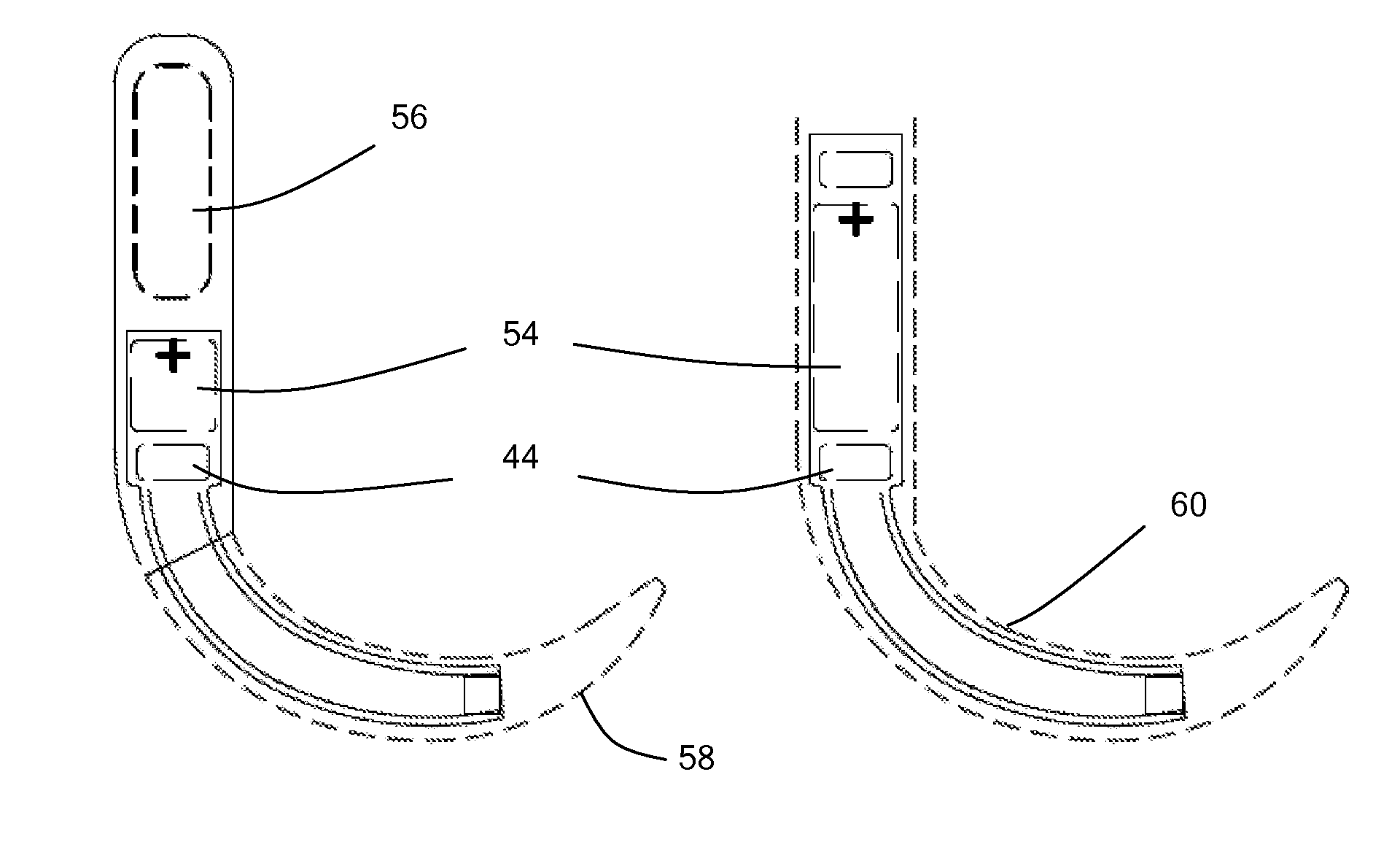
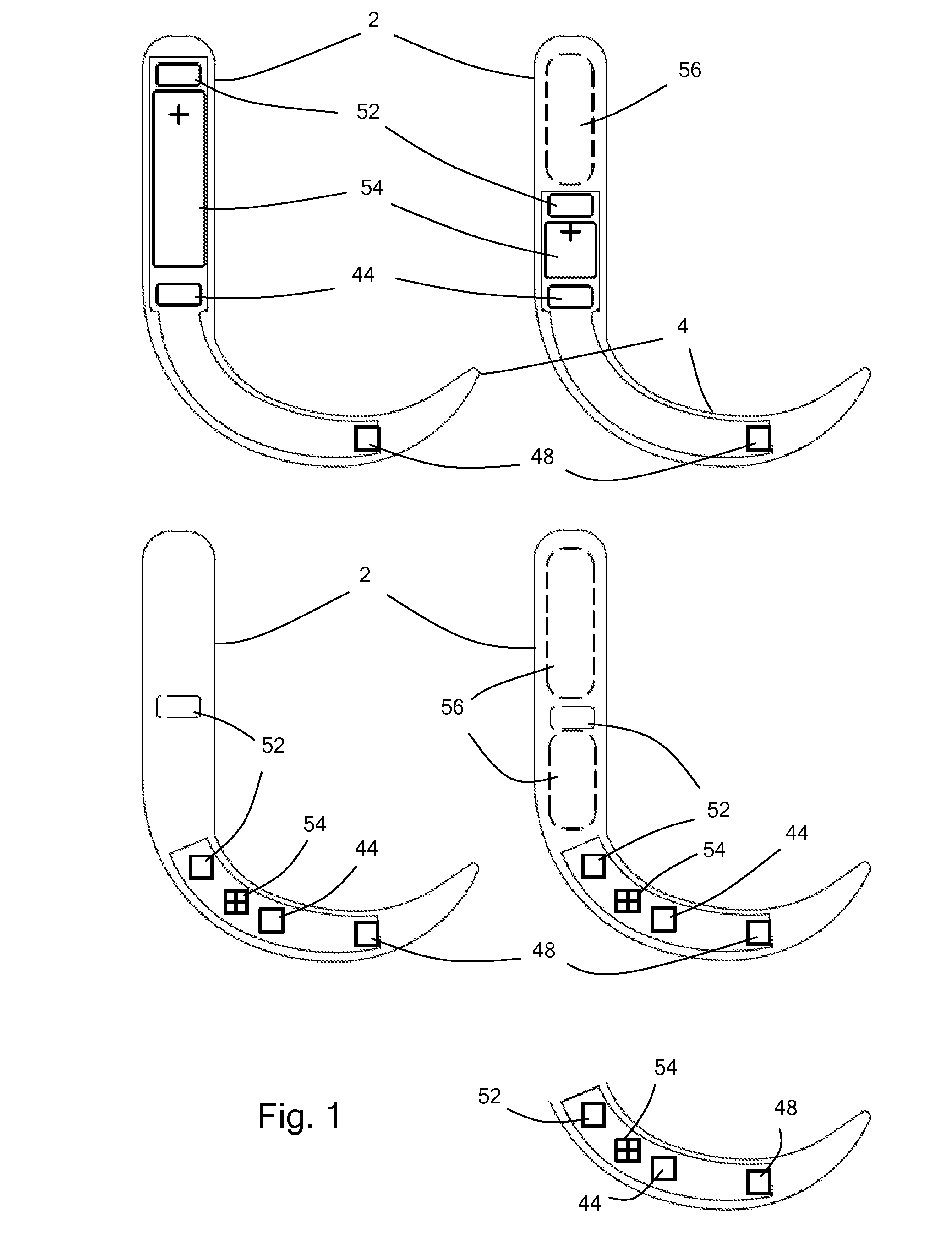
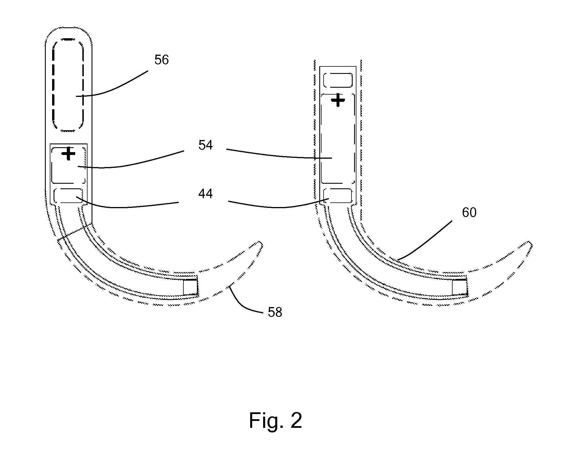
[0051]With reference to FIG. 1 a video laryngoscope 1 (being an example of an electrical device) comprises a body 2, and an arm 4 extending from the body. When prepared for use, a disposable rigid plastic sheath 58 or 60 is demountably retained on the arm, functioning as a laryngoscope blade.

[0052]The body of the video laryngoscope includes a processor unit 44 which comprises a memory unit and controls the functions of the video laryngoscope, including a light 46, a video camera 48, a video display 50 for displaying images from the video camera via a wired connection (acting as a connector) 52 and a battery 54 to provide power for the video laryngoscope. The surface of the body comprises an activation switch 22 and a light emitting diode 24 which functions as a display informing the user whether the video laryngoscope is activated.

[0053]The video laryngoscope further comprises an air gap 56 (acting as a low density portion) at the end of the body opposed to the arm.

[0054]In alternat...

second embodiment

[0063]With reference to FIGS. 2 to 5 a video laryngoscope 1 (being an example of an electrical device) comprises a body 2, and an arm 4 extending from the body. When prepared for use, a disposable rigid plastic sheath (not shown) is demountably retained on the arm, functioning as a laryngoscope blade. The body portion comprises a first surface region 6, and a recess 8 for receiving a battery pack 10.

[0064]The body comprises electrical contacts 12 (functioning as an input interface) for receiving electrical power from the battery pack, located within the recess. The battery pack comprises a first major surface 14 and a second, opposed major surface 16. The first major surface comprises battery retaining formations 18 which retain a battery 20 and, when the battery pack is installed on the body the first major surface faces the body. The second major surface comprises an activation switch 22 and a light emitting diode 24 which functions as a display informing the user whether the vide...


PUM

PropertyMeasurementUnit
electrical propertiesaaaaaaaaaa
external poweraaaaaaaaaa
poweraaaaaaaaaa

Abstract

An electrical device includes a memory storing a value indicative the remaining available rated capacity of one or more batteries. The stored value is changed in use to reflect reducing capacity. The initial stored value is chosen so that there is a very high (e.g. >99.9%) confidence that the one or more batteries will provide at least the capacity indicated by the initial stored value. This reduces the chance of failure during emergency procedures. The one or more batteries may be integral to the electrical device. An override facility is provided.

Description

FIELD OF THE INVENTION[0001]The invention relates to electrical devices, including electrical medical devices, which are powered by batteries and which are operated in environments where they may come into contact with liquid.BACKGROUND TO THE INVENTION[0002]Electrical devices, such as electrical medical devices, may incorporate a battery power supply to enable them to be used without the limitations of a power cable.[0003]A known problem with battery powered electrical devices, including electrical medical devices such as laryngoscopes, is that the batteries may be depleted and the power supply may fail during use. The battery compartments of such devices will typically receive any of a wide range of batteries having a similar external shape but substantially different electrical properties and capacities. Furthermore, it may not be apparent if a battery has been used before. Thus, it may not be possible to predict exactly when the power supply may fail. Thus, in many known devices...

Claims


Application Information

Patent Timeline
Patent Type & Authority Applications(United States)
IPC IPC(8): G01R31/36A61B1/267A61B1/04H01M50/209
CPCA61B1/00034A61B1/267G01R31/3606H01M2/08H01M2/1066A61B1/04H01M6/50H01M6/5044H01M10/48H01M10/488A61B1/00029H01M2/1094G01R31/382Y02E60/10H01M50/209H01M50/24H02J7/0048G01R31/3648A61B1/00025
Inventor MCGRATH, MATTHEW JOHN ROSSINGLIS, PETER DOUGLAS COLINLAFFOLEY, BRIAN ALAN
Owner COVIDIEN AG
Learn More