
Printhead for inkjet printing device

Active Publication Date: 2013-03-14
EASTMAN KODAK CO
View PDF3 Cites 22 Cited by
  • Summary
  • Abstract
  • Description
  • Claims
  • Application Information

AI Technical Summary

Benefits of technology

The present invention provides an inkjet printhead with improved chemical resistance and thermally stability. This is achieved by applying a chemically resistant and thermally stable multilayer coating onto the printhead, which includes one or more thin film layers comprised primarily of hafnium oxide, zirconium oxide, or tantalum oxide. The multilayer coating can be formed using film forming methods that produce conformal films that cover complex geometries, enabling the coating to be formed on all surfaces of the printhead that come in contact with inks or other fluids employed in the printing system. This results in improved printhead durability and reliability for higher printing efficiency and performance.

Problems solved by technology

The resistive heaters in thermally actuated drop on demand inkjet printheads operate in an extremely harsh environment.
They must heat and cool in rapid succession to enable the formation of drops usually with a water based ink with a superheat limit of approximately 300° C. Under these conditions of cyclic stress, in the presence of hot ink, dissolved oxygen, and possibly other corrosive species, the heaters will increase in resistance and ultimately fail via a combination of oxidation and fatigue, accelerated by mechanisms that corrode the heater or its protective layers (chemical corrosion and cavitation corrosion).
It is known to those skilled in the art that the resistive heating element employed in the drop forming mechanism of a thermally actuated drop on demand inkjet printhead can fail because of cavitation processes and thermally activated corrosion processes occurring during operation of the inkjet printhead with the ink, printing fluid, or cleaning fluids employed in the printing system.
While the inkjet printer disclosed in Chwalek et al. works extremely well for its intended purpose, using a heater to create and deflect ink droplets increases the energy and power requirements of this device.
It is known to those skilled in the art that increased energy and power dissipated in an inkjet printhead increases the possibility of printhead failure caused by thermally activated corrosion and cavitation processes that occur during the operation of the inkjet printhead in contact with the ink, printing fluid, or cleaning fluid.
It is known to those skilled in the art that the thermally actuated resistive heating elements disclosed as part of the drop forming mechanism can become non-functional as a result of thermally activated corrosion processes that occur when the inkjet printhead is operated in contact with the ink, printing fluid, or cleaning fluid employed in the printing system.
It is known, then, that both drop on demand printheads and continuous inkjet printheads are subject to corrosion and wear during use as a result of exposure to inks and other fluids employed in printing systems.
The printhead in both drop on demand and continuous inkjet printing apparatus is in continual contact with ink and it has been found that both drop on demand and continuous inkjet printheads are degraded over time by continual contact with ink and other fluids employed in printing apparatus.
It is known to those skilled in the art that the material layer of the printhead, as well as the drop forming mechanism in or on the material layer, is also susceptible to chemical corrosion processes and that an additional pathway available for printhead failures involves failure of the material layer and any associated electrical circuitry as a result of corrosion of the material layer or any element thereof.
The authors specifically remarked, however, that they observed “no clear tendency to improve performance by increasing the number of layers”.
One type of failure described above that can require printhead replacement is related to corrosion, chemical dissolution, and optionally cavitation induced failure of thermally actuate resistive heating elements in the printhead drop forming mechanism.
It is also known that other heated and unheated surfaces of the printhead such as those located anywhere on the material layer of the printhead including surfaces of integrated circuits incorporated on the printhead material layer that have the possibility of exposure to ink or other fluids used in a printing system can corrode upon exposure to the inks and fluids employed in a digitally controlled printing system.
Corrosion of surfaces on or proximate to the material layer can result in the printhead becoming non-functional.

Method used


Image

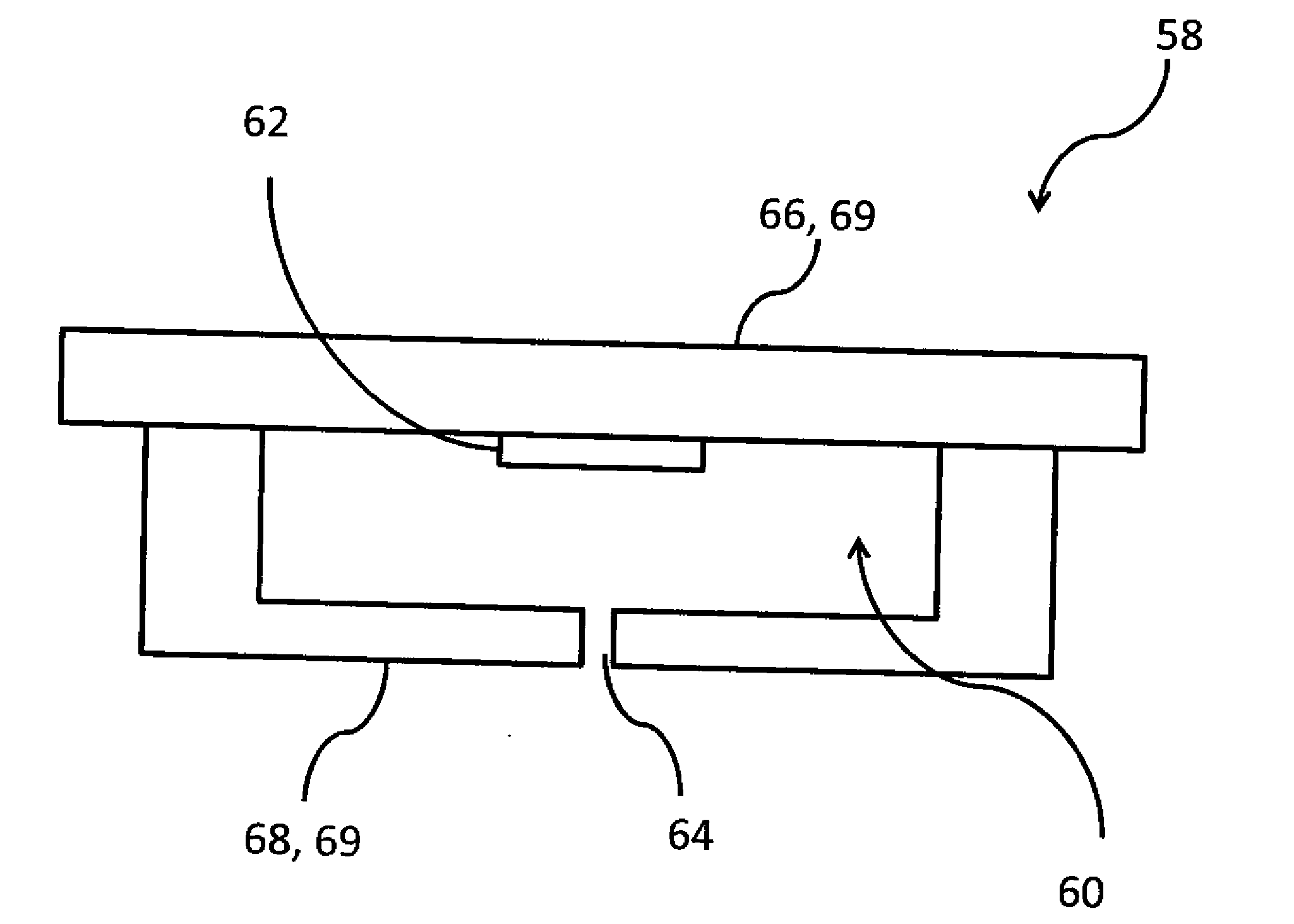
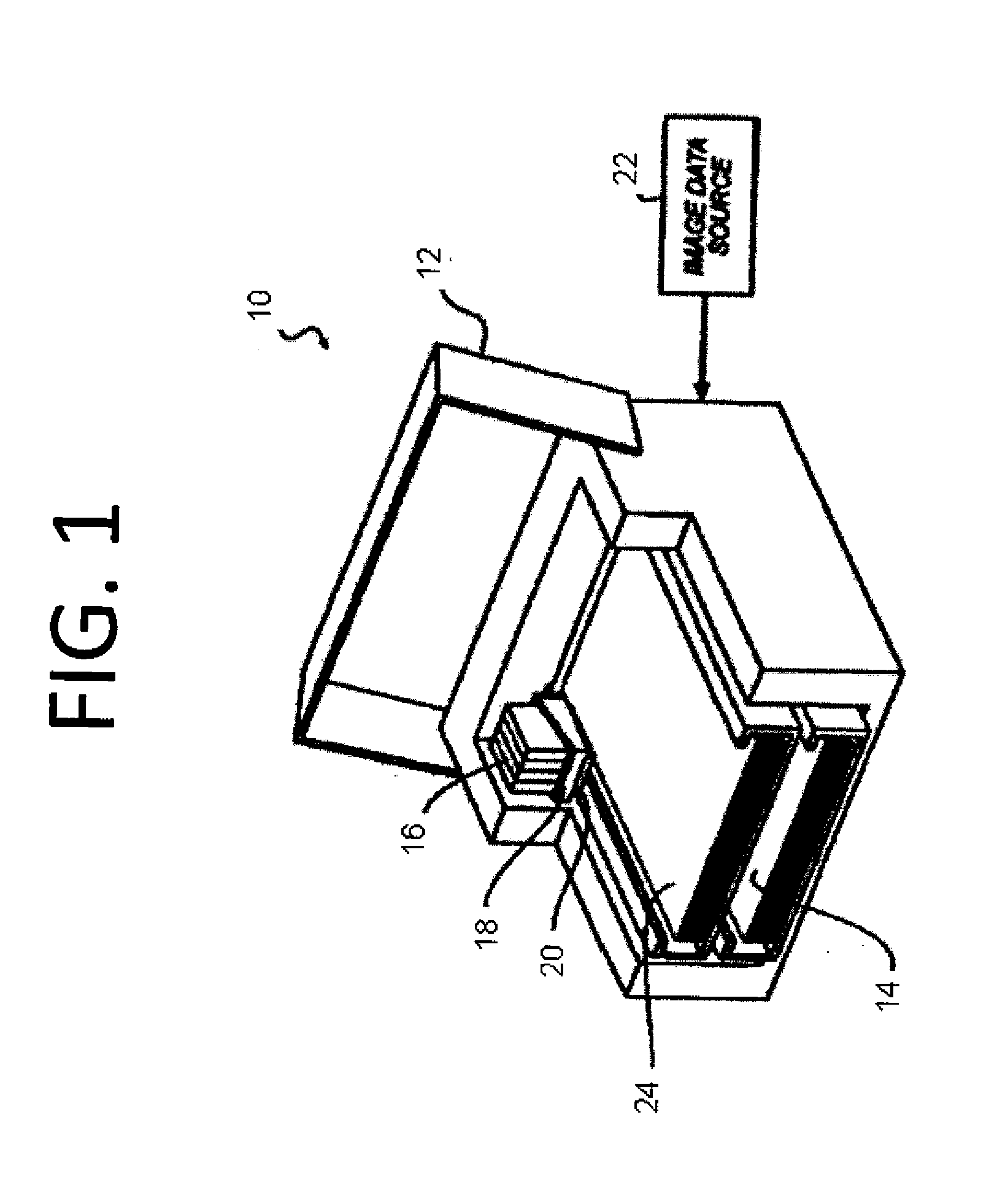
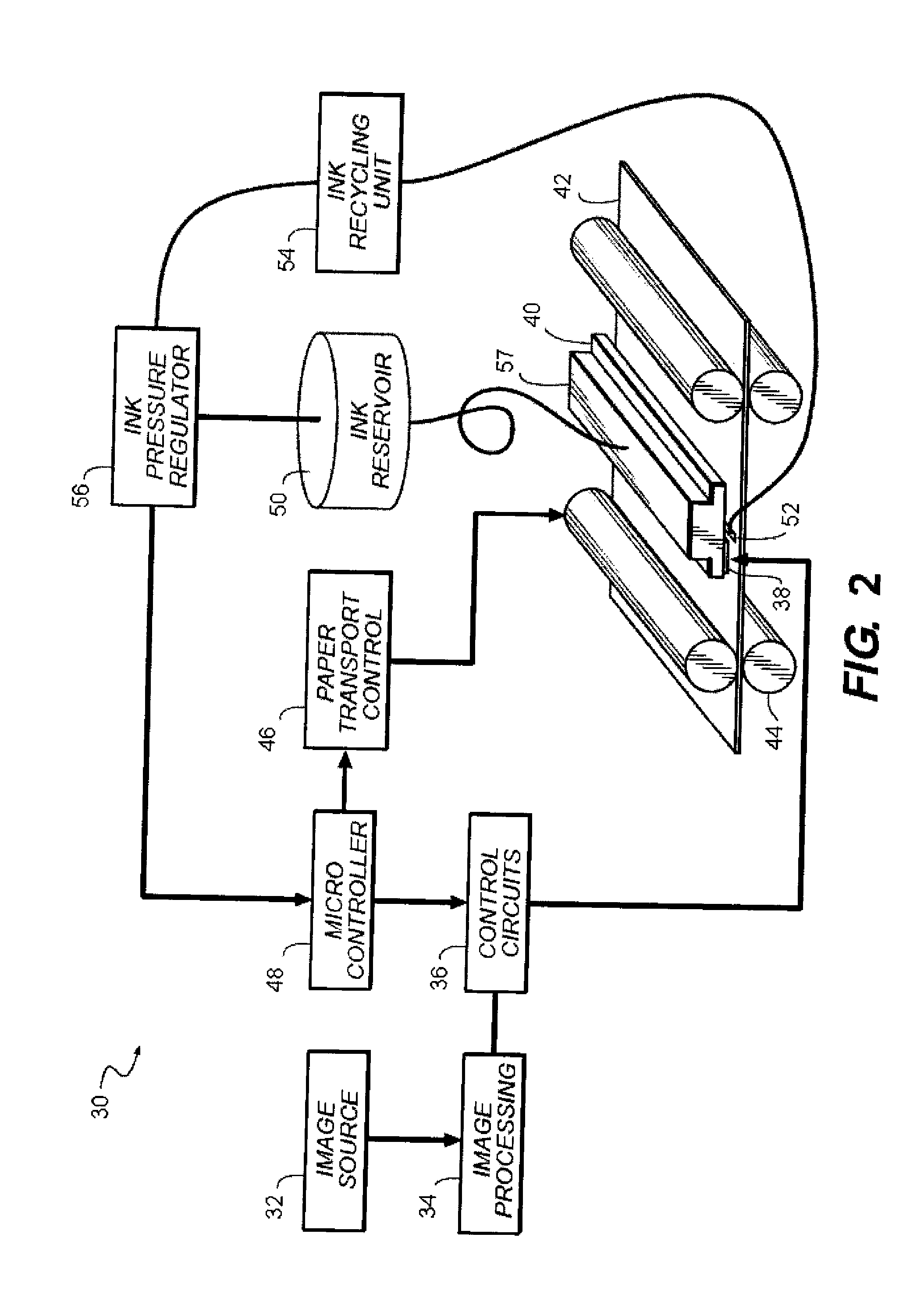
  • Printhead for inkjet printing device
  • Printhead for inkjet printing device
  • Printhead for inkjet printing device

Examples


example 1a-1f

[0070]This example demonstrates the use of an adhesion promoting layer in combination with an improved corrosion resistant laminate film comprised of multiple layers each consisting essentially of HfO2 or Ta2O5, and demonstrates at least one preferred composition of a corrosion resistant laminate as described in the invention. This example also demonstrates that the relative thickness, order and number of the refractory oxide layers in the invention is important with regard to achieving optimal results, and that the observed improved corrosion resistance of the laminate films, and in particular of hafnium oxide rich HfO2—Ta2O5 laminate films, is novel and could not have been predicted.

[0071]In examples 1A-1F the 200 nm of silicon oxide layer of the silicon wafer substrate described above is an adhesion promoting layer that enables corrosion resistant surface coatings and films that are deposited on top of the silicon wafer to adhere well to the wafer substrate. The outermost layer o...

example 2

[0075]This example demonstrates the use a wear and abrasion resistant coating on a chemically resistant, corrosion resistant laminate film as described in an embodiment of the invention.

[0076]Two silicon wafers with multilayer corrosion resistant films identical to example 1C were fabricated and one of the wafers was overcoated with 400 nm of an abrasion resistant coating containing silicon, nitrogen, and carbon at 320° C. The overcoat film containing silicon, nitrogen and carbon was prepared by chemical vapor deposition methods like those described by Bau et al (S. Bau, S. Janz, T. Kieliba, C. Schetter, S. Reber, and F. Lutz; WCPEC3-conference, Osaka, May 11-18(2003); “Application of PECVD-SiC as Intermediate Layer in Crystalline Silicon Thin-Film Solar Cells”). The 200 nm of silicon oxide layer on the silicon wafer substrate is an adhesion promoting layer that is at least 0.2 nm in thickness and enables corrosion resistant surface coatings and films that are deposited on top of th...

example 3

[0077]This example demonstrates the use of an adhesion promoting layer in combination with a corrosion resistant laminate films comprised of multiple layers each consisting essentially of ZrO2 or Ta2O5. This example also demonstrates corrosion resistant laminate films where a thin film layer of ZrO2 is substituted for HfO2 in the laminate and where HfO2 and ZrO2 are both present as thin films in a laminate structure along with Ta2O5. In addition, this example demonstrates at least one additional preferred composition of a corrosion resistant laminate as described in the invention.

[0078]The outermost layer of the wafer substrates in examples 3A-3E, comprised of a SiO2 adhesion promoting layer, was then coated with a corrosion resistant film. Various types of corrosion resistant films were deposited for evaluation and the various films are given in examples 3A through 3E. Films in examples 3A-3E were deposited by atomic layer deposition methods using the methods described by Liu et al...


PUM

PropertyMeasurementUnit
Thicknessaaaaaaaaaa
Thicknessaaaaaaaaaa
Thicknessaaaaaaaaaa

Abstract

An inkjet printhead is provided for a digitally controlled inkjet printing apparatus wherein the inkjet printhead is comprised of a material layer and a drop formation mechanism positioned in or on the material layer, that is substantially improved in chemical resistance and thermally stability. A chemically resistant and thermally stable multilayer coating is provided onto and in contact with the inkjet printhead, wherein the multilayer coating includes one or more thin film layers comprised primarily of hafnium oxide or zirconium oxide and one or more thin film layers comprised primarily of tantalum oxide, the multilayer coating being located on the material layer. The corrosion resistant film of the invention is particularly beneficial because it can be formed on the printhead using atomic layer deposition film forming methods that produce conformal films that cover complex geometries, thereby enabling the corrosion resistant film to be formed on all surfaces of the printhead that come in contact with inks or other fluids employed in the printing system.

Description

CROSS-REFERENCE TO RELATED APPLICATIONS[0001]Reference is made to commonly assigned U.S. Ser. No. ______ (Kodak Docket K000591) filed concurrently herewith, directed towards “Microfluidic Device With Multilayer Coating,” the disclosure of which is incorporated by reference herein in its entirety.FIELD OF THE INVENTION[0002]This invention relates generally to the field of digitally controlled printing devices, and in particular to printheads for digitally controlled inkjet printing devices where chemically resistant thin film layers are applied to the inkjet printhead for the purpose of improving the operation of the printing system.BACKGROUND OF THE INVENTION[0003]Inkjet printing has become recognized as a prominent contender in the digitally controlled, electronic printing arena. Among the many advantages of inkjet printing is its non-impact, low-noise characteristics, its use of plain paper, and its avoidance of toner transfers and fixing. Inkjet printing mechanisms can be categor...

Claims


Application Information

Patent Timeline
IPC IPC(8): B41J2/14
CPCB41J2/03B41J2/14129B41J2/1601C23C16/405B41J2/1642B41J2/1646B41J2202/22B41J2/1606
Inventor SIEBER, KURT D.
Owner EASTMAN KODAK CO
Learn More