
Electrically operated valve actuator with electro-mechanical end stop detection device

a technology of electromechanical end stop and valve actuator, which is applied in the direction of valve operating means/release devices, mechanical equipment, and wellbore/well accessories, etc., and can solve problems such as motor damage, motor loss protection, and winding of the stator burning

Inactive Publication Date: 2013-03-07
VETCO GRAY SCANDINAVIA
View PDF10 Cites 10 Cited by
  • Summary
  • Abstract
  • Description
  • Claims
  • Application Information

AI Technical Summary

Benefits of technology

The present invention is about a fail-safe end stop detection and over-heating protection for the motor of an electrically operated valve actuator. The invention provides a solution by designing the movable member of the valve with an idling length of travel in the opening and closing directions during which the valve is either fully open or fully closed. An electro-mechanical end stop detection device is provided that allows for an early detection of the end position, and the mechanical part of the solution provides a physical space and time window during which the increase in supplied current can be monitored and the motor be stopped, in a controlled manner. This invention helps avoid the requirement for an instantaneous reaction of the control circuit which is necessary in other types of electrically operated valve actuators. The end stop device can be used as a primary or secondary control means, and in some applications it may also act as a means for calibration of a primary position sensor in the valve actuator. The buffer means used in the invention can be disc springs, which provide a controlled flexibility within the idling length of travel of the movable member and a corresponding typical increase in current required by the motor during the idling travel length.

Problems solved by technology

If the current supply to the stator is not controlled, the stator windings will burn and the motor is destroyed.
However, if the position sensor is offset or otherwise fails, the current control is set aside and the motor looses protection from overheating.

Method used


Image

  • Electrically operated valve actuator with electro-mechanical end stop detection device
  • Electrically operated valve actuator with electro-mechanical end stop detection device

Examples


Embodiment Construction

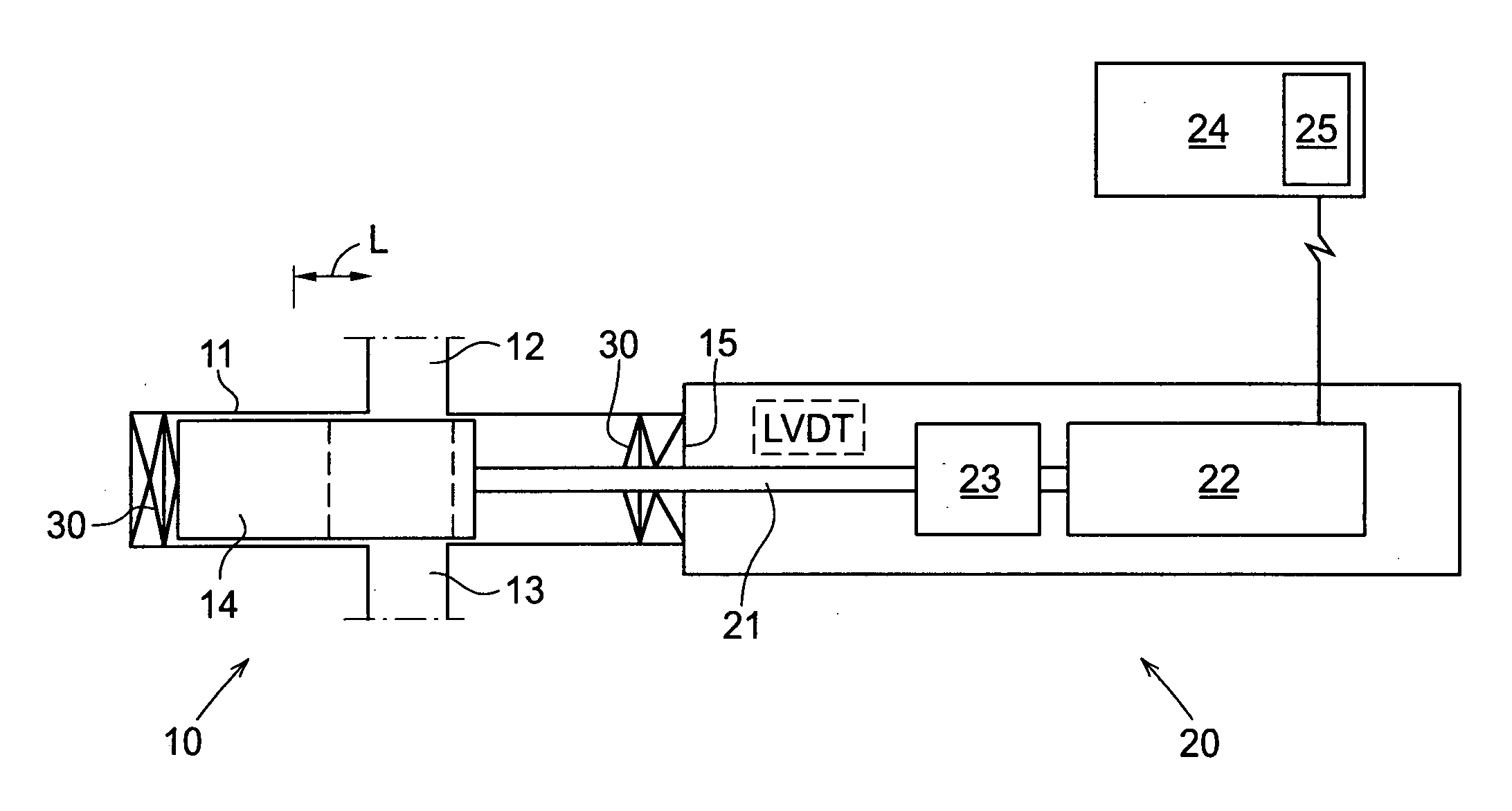
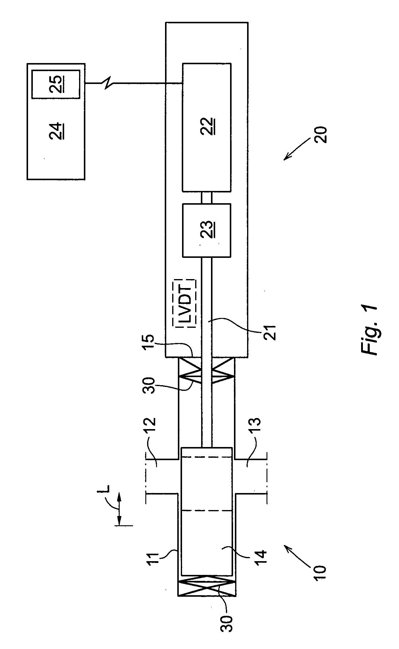
[0013]The invention is illustrated schematically in the drawing (FIG. 1). With reference to the drawing, a valve generally indicated by reference sign 10 is shiftable between open and closed positions by means of a valve actuator generally indicated by reference sign 20. The valve 10 comprises a valve housing 11 having inlet port 12 and outlet port 13 for fluid flow in the open position of the valve (illustrated position). The fluid flow through the valve 10 is controlled by a valve body 14 which is linearly movable in the housing between open and closed positions. The shifting and positioning of the valve body 14 is accomplished by a movable stem 21, which enters through a wall 15 of the valve / actuator housing and connects to the valve body. The stem 21 is driven in reciprocating motion by an electrical motor 22, via an Rotary-To-Linear-converter 23 that converts the rotary motion of the motor to a linear motion of the stem. The motor 22 is supplied electrical power from a power so...


PUM


Abstract

An electrically operated valve actuator effective for shifting a valve (10) between open and closed positions is disclosed, the valve actuator comprising a movable member in the form of a valve stem (21) connected to a valve body (14), the movable member being driven by an electric motor (22) in linear motion between valve closing and valve opening positions, wherein electrical power to the motor is supplied via a current (25) control including a supplied current detection device. The movable member is designed for an idling length of travel (L) in the opening and closing directions during which the valve (10) is either fully open or fully closed, and the movable member is associated with buffer means (30) that during the idling length of travel gradually increases the torque and power required to move the movable member further in the open and closed positions of the valve (10), respectively.

Description

TECHNICAL FIELD OF THE INVENTION[0001]The present invention relates to an electrically operated effective for shifting a valve between open and closed positions, valve actuator comprising a movable member in the form of a valve stem connected to a valve body, the movable member being driven by an electric motor in linear motion between valve closing and valve opening positions, wherein electric power to the motor is supplied via a current control including a supplied current detection device.BACKGROUND AND PRIOR ART[0002]In the subsea industry, valves are traditionally activated by hydraulic devices. In a hydraulic actuator, end stop detection and control meet no problem as it is the nature of a hydraulic system. When the end of travel is reached, the valve stem stops and the hydraulic pressure is returned to normal working pressure.[0003]In electrically operated valve actuators this is quite different. The torque of the motor is proportional to the current supplied. If the rotor of...

Claims


Application Information

Patent Timeline
Patent Type & Authority Applications(United States)
IPC IPC(8): F16K31/02
CPCF16K31/04F16K3/0254F16K31/047F16K37/0041F16K31/045F16K31/048F16K31/0689F16K31/0696H01H35/06
Inventor BORCHGREVINK, CHRISTIANFLIDH, JON
Owner VETCO GRAY SCANDINAVIA
Learn More