
Exchanger-reactor for the production of hydrogen with an integrated steam generation bundle

a technology of exchangers and reactors, applied in steam generation plants, steam generation using hot heat carriers, thermal naphtha reforming, etc., can solve the problems of affecting the pipe diameter has to be even larger, and the overall efficiency of the system is penalized

Inactive Publication Date: 2013-02-28
INST FR DU PETROLE
View PDF14 Cites 1 Cited by
  • Summary
  • Abstract
  • Description
  • Claims
  • Application Information

AI Technical Summary

Benefits of technology

The present invention is a reactor for carrying out endothermic reactions, which includes a peripheral space containing steam generation tubes and a shell enclosing the tubes. The reactor also has a plurality of suspended bayonet tubes for carrying out the endothermic chemical reaction. The reactor is designed to efficiently transfer flue gas from the reactor to the steam generation tubes, allowing for efficient use of heat. The reactor can be used for processes such as steam reforming of oil, natural gas, or alcohol. The reactor has a low peripheral volume and provides a compact design for industrial applications.

Problems solved by technology

When using an exchanger-reactor with flue gas under pressure (typically in the range 2 to 5 bar relative), it becomes very difficult to connect the flue gas outlets when they are at temperatures over 550° C. In the prior art, the interior of the pipework has to be thermally insulated so that the flange is at a sufficiently low temperature, but that embodiment means that the pipe diameter has to be even larger, which can lead to mechanical problems with the shell of the exchanger-reactor which itself has to remain at a relatively low temperature (typically below 300° C.) in order to remain economically viable.
However, that flue gas drop line also has to be internally insulated, making it bulky and expensive.
Further, it is a source of heat losses which penalize the overall efficiency of the system.

Method used


Image

  • Exchanger-reactor for the production of hydrogen with an integrated steam generation bundle
  • Exchanger-reactor for the production of hydrogen with an integrated steam generation bundle
  • Exchanger-reactor for the production of hydrogen with an integrated steam generation bundle

Examples


Embodiment Construction

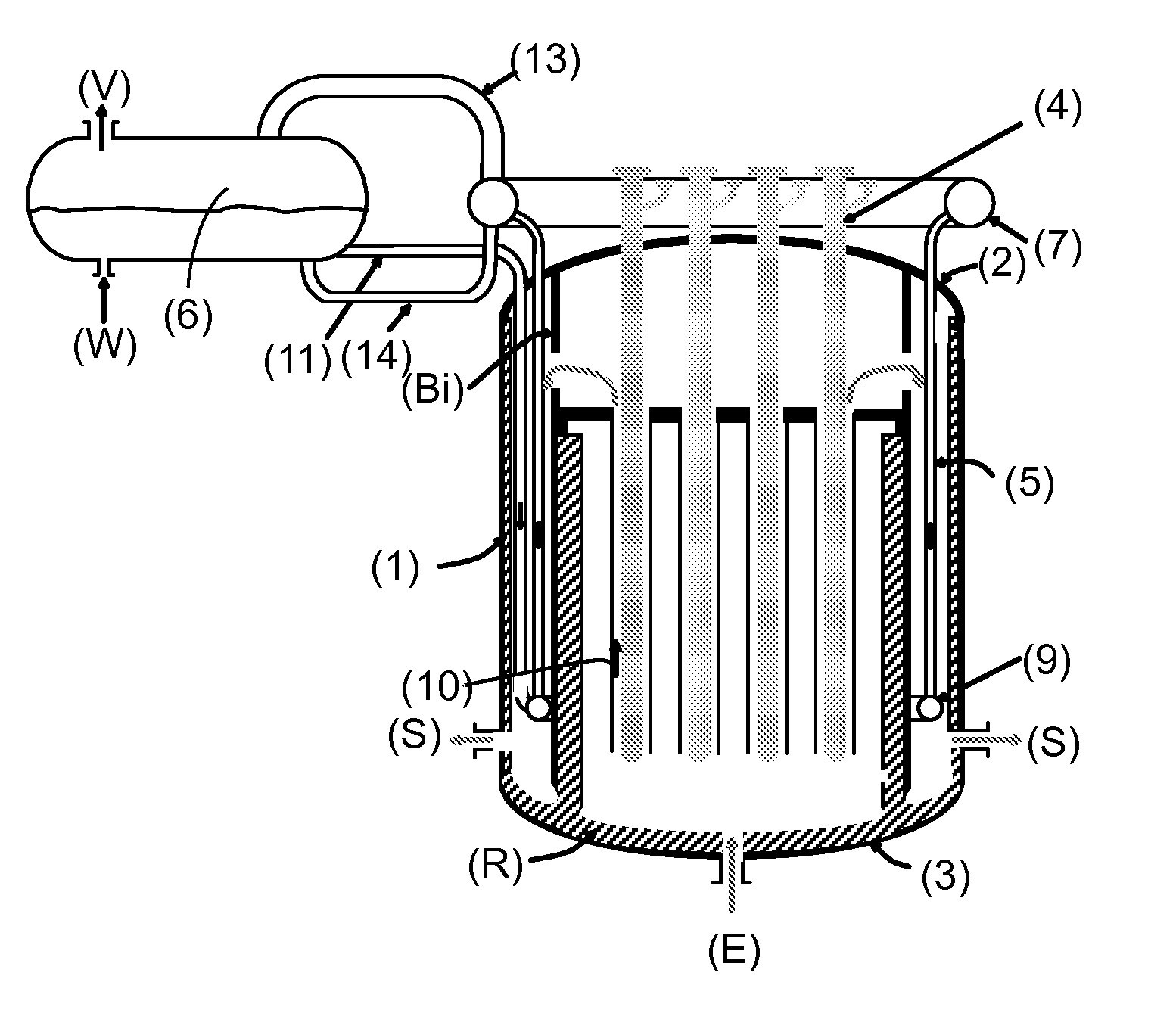
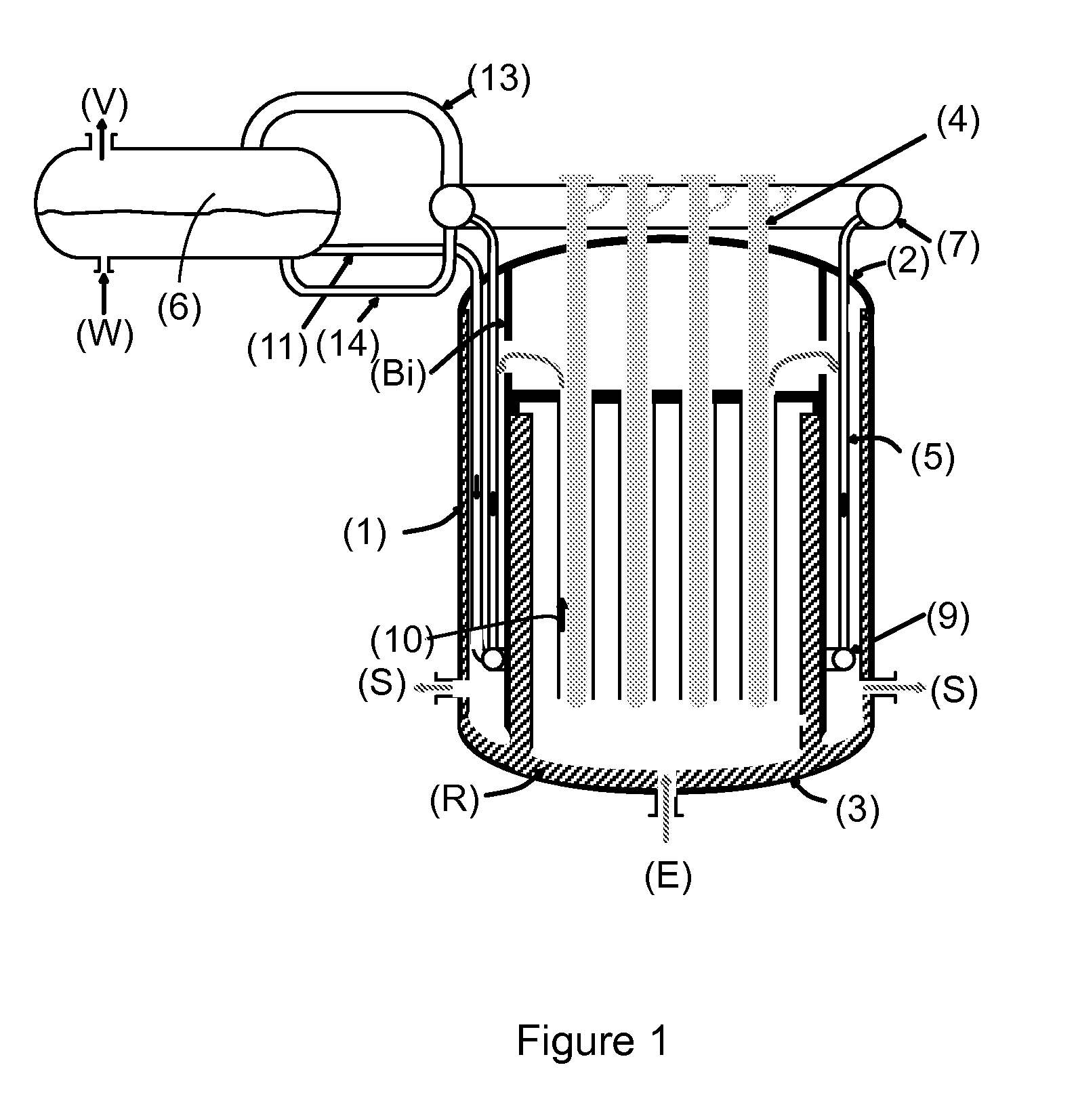
[0026]The present invention may be defined as an exchanger-reactor with improved energy efficiency due to the positioning of a steam generation bundle which is completely integrated into said reactor, i.e. placed in a peripheral space with respect to with the core of the reactor occupied by the bundle of bayonet tubes, meaning that the flue gas can be exhausted better.

[0027]The solution of the invention consists of cooling the flue gas after their first exchange with the bayonet tubes (4) for carrying out the chemical reactions of the process, thereby generating steam before leaving the exchanger-reactor (1) in a space (8) located at the periphery of the exchanger-reactor.

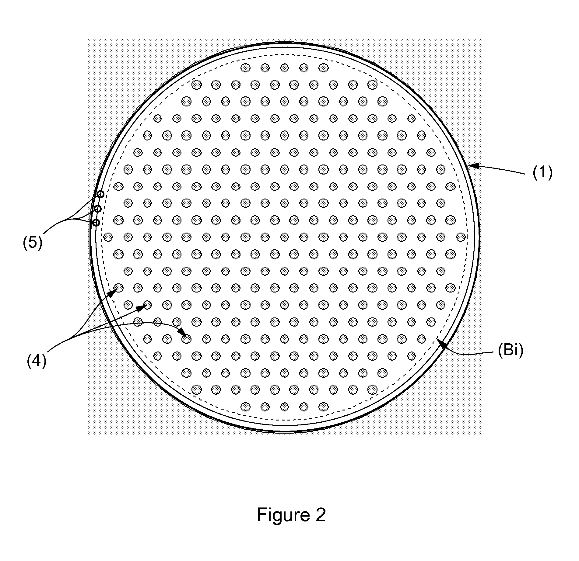
[0028]To this end, vertical steam generation tubes (5) are installed at the periphery of the exchanger-reactor (1) inside the peripheral space (8) defined on the one hand by an internal substantially vertical baffle Bi extending from the lower bottom (3) to the upper dome (2), and on the other hand by the vertical ...


PUM

PropertyMeasurementUnit
velocityaaaaaaaaaa
velocityaaaaaaaaaa
temperatureaaaaaaaaaa

Abstract

The present invention describes an exchanger-reactor for carrying out endothermic reactions such as steam reforming oil cuts or alcohols integrating a steam generation bundle which can thereby increase the thermal efficiency.

Description

FIELD OF THE INVENTION[0001]The present invention relates to the field of exchanger-reactors for carrying out endothermic reactions such as steam reforming oil cuts or alcohols, with a view to the production of synthesis gas.[0002]That type of reactor is known in the art; descriptions can be found in patents U.S. Pat. No. 4,919,844, U.S. Pat. No. 4,690690, WO 2003 031050 and WO 03 / 035242.[0003]The principal of such an exchanger-reactor diagrammatically consists of moving hot flue gas, which can reach 1200° C. at the reactor inlet, around a set of tubes inside which an endothermic reaction or a series of generally endothermic reactions is occurring. The thermal efficiency of such an exchanger-reactor is essentially determined by the outlet temperature of the flue gas.[0004]The aim of the present invention is to improve the thermal efficiency of such an exchanger-reactor by reducing the outlet temperature of the flue gas by integrating a suitably disposed steam generation bundle into ...

Claims


Application Information

Patent Timeline
Patent Type & Authority Applications(United States)
IPC IPC(8): B01J19/14C07C5/00C07C37/00C10G35/02
CPCB01J8/067C01B3/323C01B3/384F22B33/18B01J2208/00212Y02E60/324C01B2203/0233C01B2203/0816C01B2203/0894F22B1/18F22B1/1838B01J2208/00221C01B2203/0811C01B2203/1241C01B2203/1217Y02P20/10B01J8/06B01J19/24B01J3/02C01B3/00Y02E60/32
Inventor BOYER, CHRISTOPHEGIROUDIERE, FABRICE
Owner INST FR DU PETROLE
Learn More