
Screw

a screw and screw body technology, applied in the direction of screws, threaded fasteners, fastening means, etc., can solve the problems of reducing the speed of screwing, reducing the screwing torque, and unable to efficiently remove the fibers contained in the object b>2/b>, so as to reduce the screwing torque and speed up the screwing speed. , the effect of rapid expulsion of cutting debris

Active Publication Date: 2013-02-28
TAIWAN SHAN YIN INT CO LTD +1
View PDF11 Cites 25 Cited by
  • Summary
  • Abstract
  • Description
  • Claims
  • Application Information

AI Technical Summary

Benefits of technology

This invention is about a screw that can clear debris quickly, reduces resistance, and promotes screwing speed. A positioning member helps the cutting edge stand on the object, and cutting planes help guide debris out of the screw's channels. This reduces the screwing torque and increases the screwing speed, without causing any protruding parts that could slow down or hinder the screw's movement. Overall, this design allows the screw to be embedded in an object properly.

Problems solved by technology

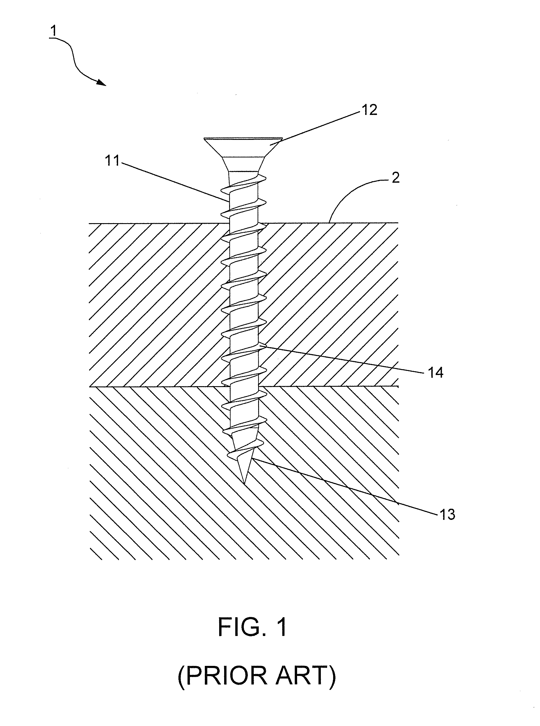
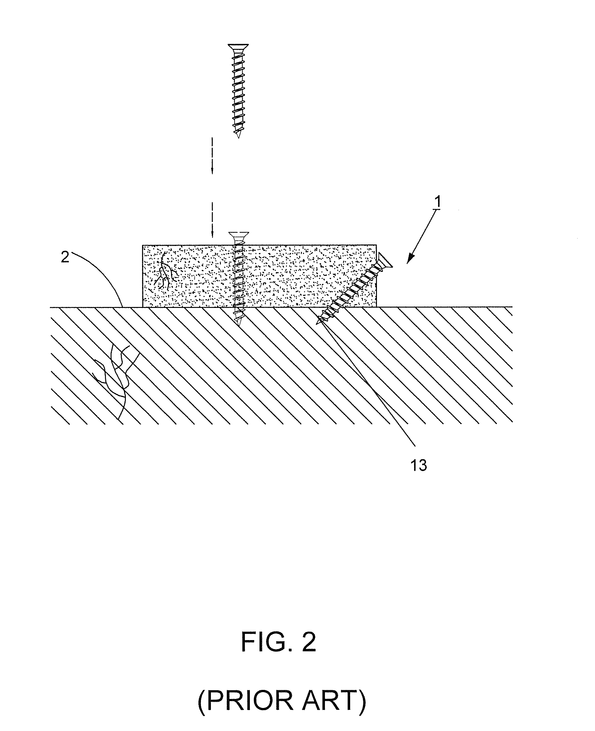
Thus, fibers contained in the object 2 are difficult to be severed efficiently.
As a result, the debris can not be timely expelled, and the heaped debris incurs an increasing resistance on the screw 1.
Such abnormal operation is unbeneficial for further fastening.

Method used


Image

  • Screw
  • Screw
  • Screw

Examples


Embodiment Construction

[0028]Wherever possible, the same reference numbers are used in the drawings and the description to refer to the same or like parts.

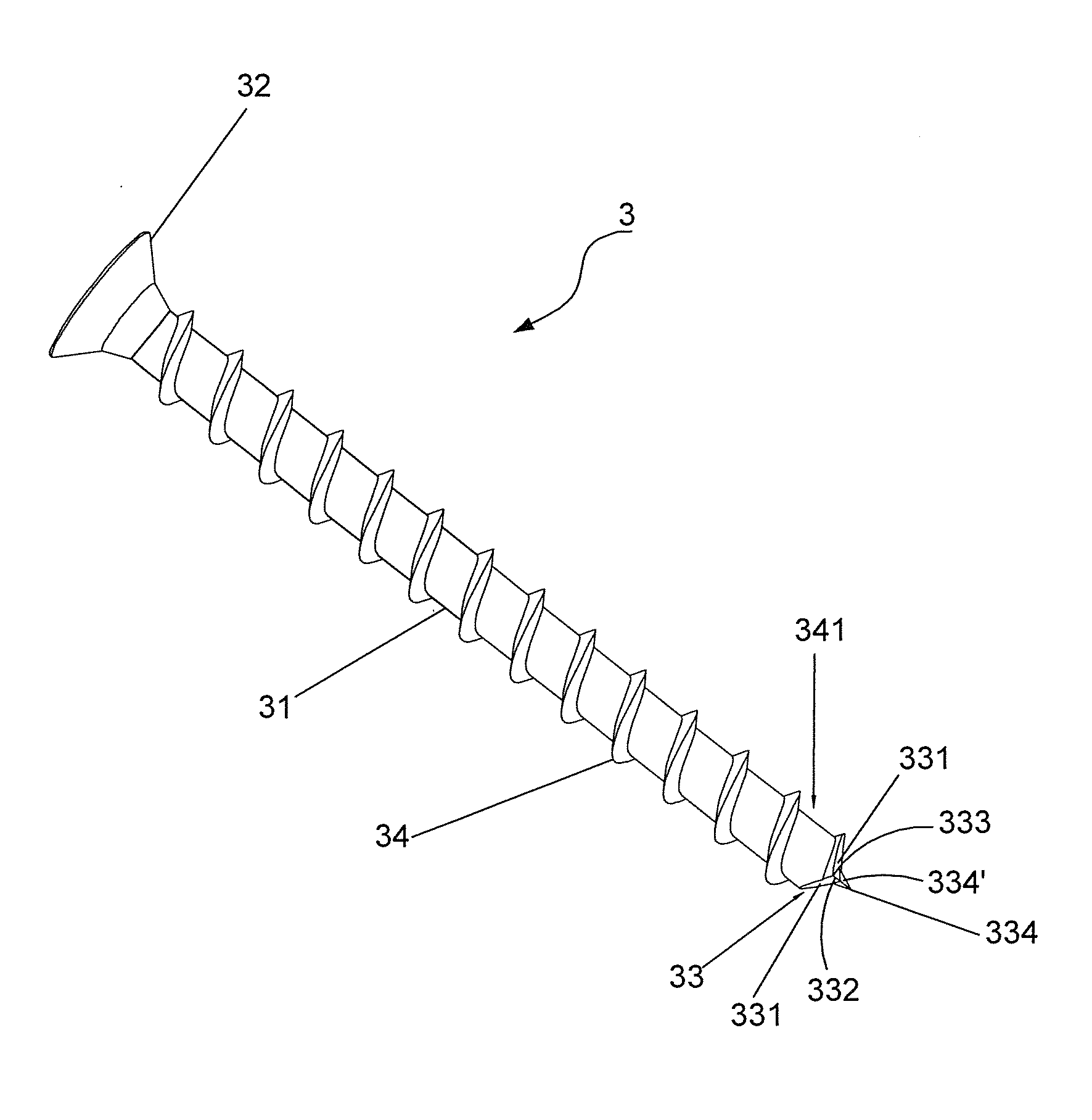
[0029]Referring to FIG. 3, a first preferred embodiment of the present invention is shown. In order to clearly show the features of the screw 3, the screw 3 in this figure and in the following embodiments is presented by one side. A screw 3 comprises a shank portion 31, a head portion 32 disposed at one end of the shank portion 31, a drilling portion 33 disposed at the other end of the shank portion 31, and a plurality of threaded units 34 surroundingly disposed around the shank portion 31. Wherein, a channel 341 is defined amid the threaded units 34. Further referring to FIG. 4, two inclined cutting planes 331 are convergently formed on the drilling portion 33, and a cutting edge 332 is formed on the convergence of the cutting planes 331. Additionally, a positioning member 334 is defined on the cutting planes 331. Herein, the positioning member 334 is ...


PUM

PropertyMeasurementUnit
diameteraaaaaaaaaa
resistanceaaaaaaaaaa
screwing resistanceaaaaaaaaaa

Abstract

A screw includes a positioning member defined on inclined cutting planes of a drilling portion of the screw for stably allowing a cutting edge constructed at a convergence of the cutting planes to cut efficiently. A threaded section formed on a shank of the screw is extended toward the cutting edge and connected with one end of the cutting edge. The positioning member helps the screw fixedly stand on an object. The cutting edge and the cutting planes allow cutting debris to be swiftly and smoothly extruded therefrom into the threaded section for avoiding the piling of the considerable cutting debris. Thereby, the screwing torque is reduced and the drilling speed is promoted. Preferably, the fastened screw is sunken in the object, and the fastening operation is completed successfully.

Description

BACKGROUND OF THE INVENTION[0001]1. Field of the Invention[0002]The present invention relates to a fastener design, particularly to a screw.[0003]2. Description of the Related Art[0004]Referring to FIG. 1, a conventional screw 1 comprises a shank portion 11, a head portion 12 disposed at one end of the shank portion 11, a drilling portion 13 disposed at the other end of the shank portion 11, and a plurality of threaded units 14 spirally disposed around the shank portion 11. Wherein, the drilling portion 13 is formed into a tapered end. Thus, the screw 1 directly enters an object 2 via the tapered drilling portion 13, and the following threaded units 14 continue entering the object 2 so as to achieve a fastening effect.[0005]Afore screw 1 might be smoothly fastened into the object 2 by means of the drilling portion 13 piercing the object 2. However, in practice, the object 2 is forcedly pierced by the tapered drilling portion 13. Thus, fibers contained in the object 2 are difficult t...

Claims


Application Information

Patent Timeline
Patent Type & Authority Applications(United States)
IPC IPC(8): F16B25/10
CPCF16B25/0015F16B25/0052F16B25/103F16B25/0068F16B25/0084F16B25/0057
Inventor SU, KOU-TSAIRSU, YU-JUNG
Owner TAIWAN SHAN YIN INT CO LTD
Learn More