
Optical film

a technology of optical film and retardation film, applied in the field of optical film, can solve the problems of 12 or 14 wavelength retardation film, restricted to limited range, etc., and achieve the effect of effective and constant production

Active Publication Date: 2013-02-21
LG CHEM LTD
View PDF7 Cites 41 Cited by
  • Summary
  • Abstract
  • Description
  • Claims
  • Application Information

AI Technical Summary

Benefits of technology

The patent text discusses a method for manufacturing an optical film with a liquid crystal layer that has good phase retardation properties and can be stably maintained. The method involves using a combination of multifunctional and monofunctional polymerizable compounds in the liquid crystal layer. This approach allows for controlled phase retardation properties in the liquid crystal layer, resulting in an optical film with improved performance. Additionally, the patent text describes a method for attaching a linear polarizer to an optical film using an adhesive layer, which ensures durability and stability of the optical film. The linear polarizer and the liquid crystal layer can also be attached using a compound with a heterocyclic acetal structure, which helps to regulate viscosity and improve adhesion strength. The manufacturing process described in the text involves producing the optical film and attaching it to the linear polarizer in a way that ensures consistent and efficient production.

Problems solved by technology

Therefore, there is a problem that ranges, within which retardation films function as the ½ or ¼ wavelength retardation film, are restricted to limited ranges.

Method used


Image

  • Optical film
  • Optical film
  • Optical film

Examples


example 1

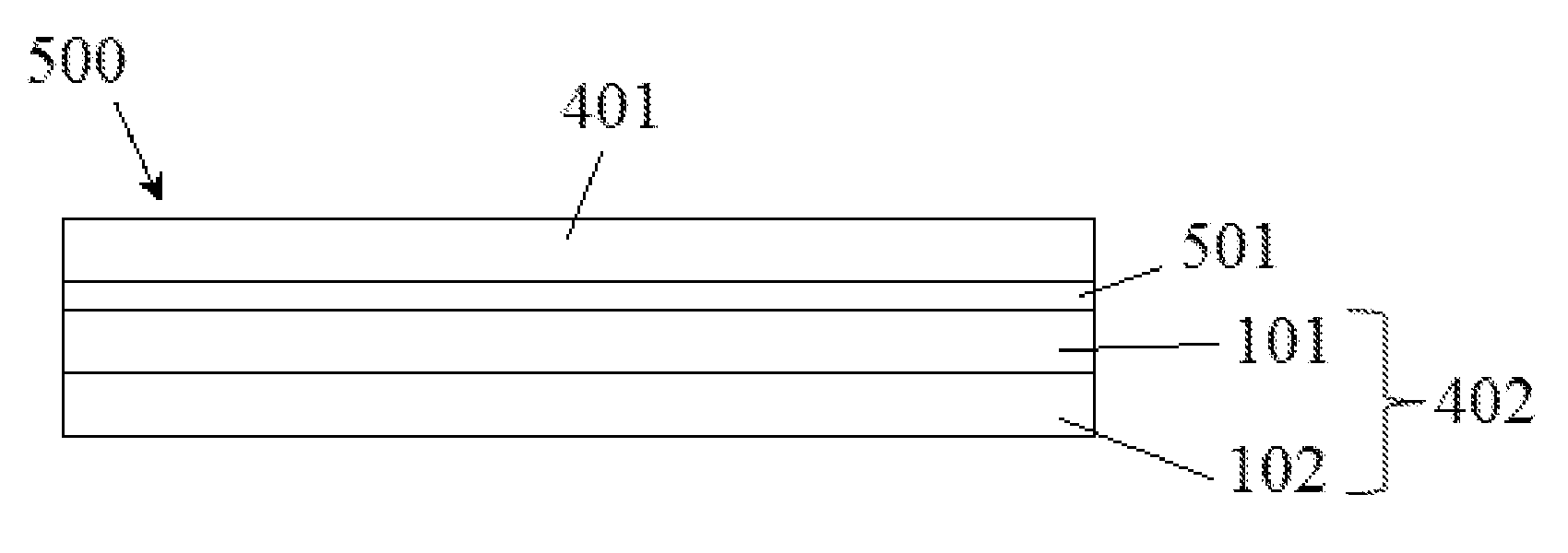
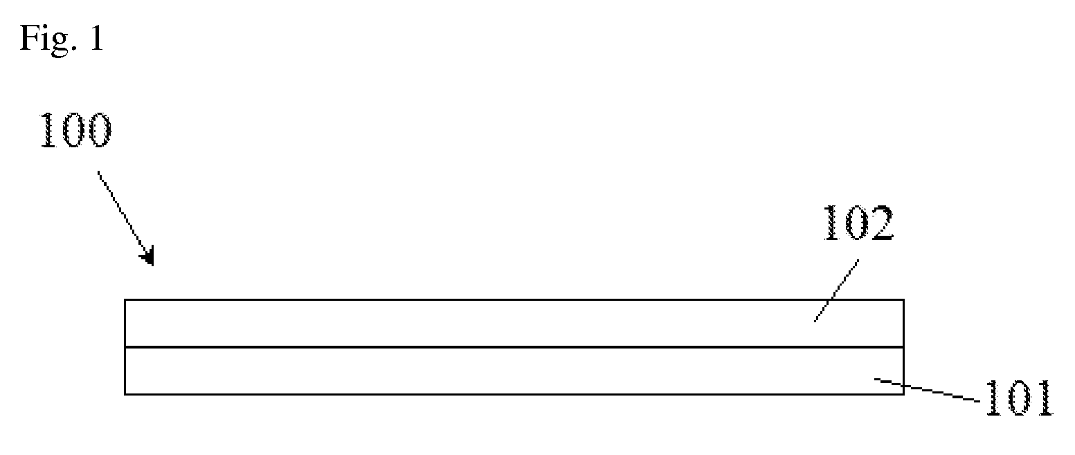
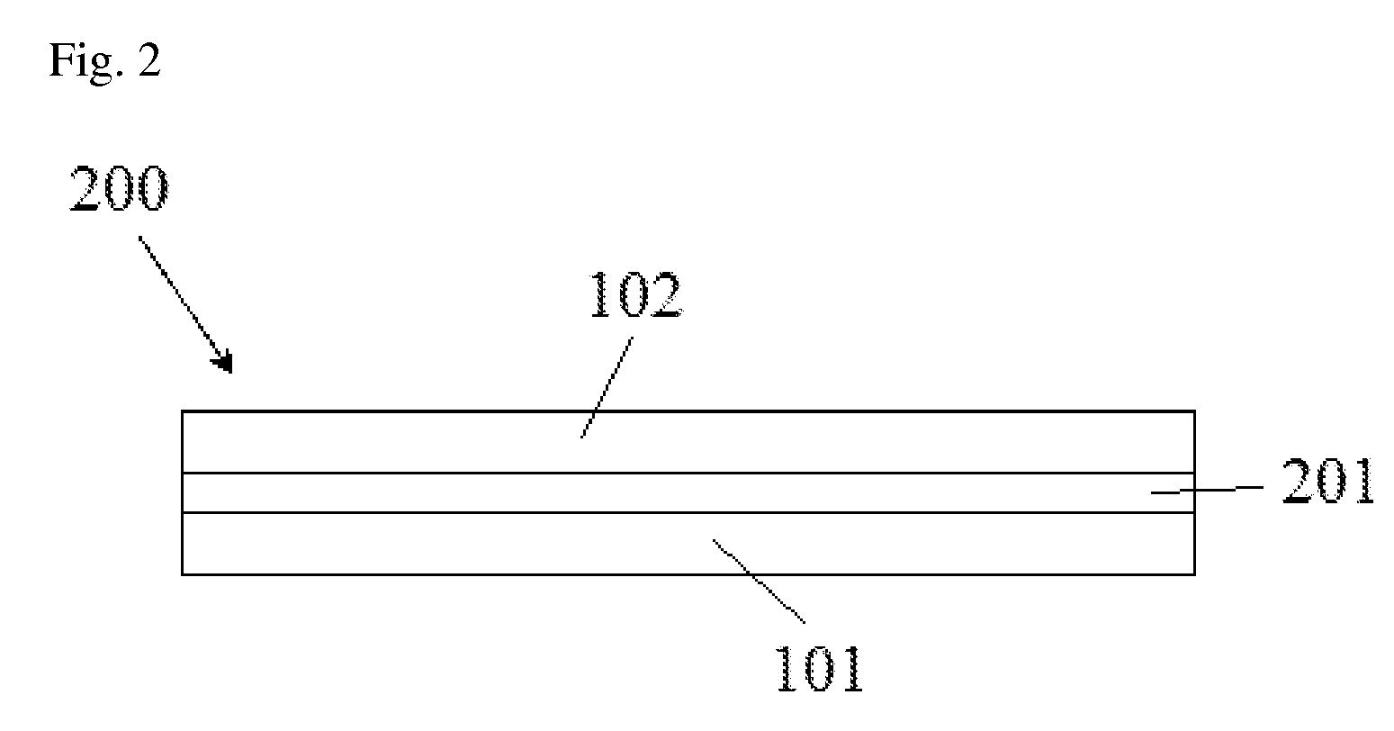
[0134]A liquid crystal layer having the in-plane phase retardation of approximately 105 nm with respect to a wavelength of 550 nm was formed on a cycloolefin polymer film having the in-plane phase retardation of 220 nm with respect to a wavelength of 550 nm as a polymeric layer by the following method.

[0135]Specifically, a composition for forming a photo-alignment layer was coated on one surface of the cycloolefin polymer film so as for the layer to have a thickness of approximately 1,000 Å after being dried, and dried in an 80° C. oven for 2 minutes. The composition for forming the photo-alignment layer was prepared by mixing a mixture of polynorbornenes (molecular weight (Mw)=150,000) having a cinnamate group represented by Formula A and acrylic monomers with photoinitiators (Igacure 907) and then dissolving the obtained mixture (polynorbornene:acryl monomer:photoinitiator=2:1:0.25 (weight ratio)) in cyclopentanone so as for the solid content of the polynorbornene to be 2 weight %...

example 2

[0138]An optical film and a circular polarizing plate were manufactured by the substantially same method as in Example 1, except that the liquid crystal layer was formed so as for the in-plane phase retardation with respect to a wavelength of 550 nm to be approximately 135 nm, the optical axis of the liquid crystal layer was controlled to be substantially perpendicular to the optical axis of the cycloolefin polymer film, and the optical axis of the cycloolefin polymer film was controlled to form an angle of approximately 45 degrees with the light absorption axis of the linear polarizer.

experimental example

[0142]An optical film and a circular polarizing plate were manufactured by the same method as described in Example 1, except that a cycloolefin polymer film having the in-plane phase retardation with respect to light with a wavelength of 550 nm of approximately 270 nm, and R(450) / R(550) of 1 or R(650) / R(550) of 1 was used as the polymer film, and the liquid crystal layer formed using a liquid crystal composition adjusted to have the in-plane phase retardation with respect to light with a wavelength of 550 nm of approximately 135 nm, R(450) / R(550) of 1.09, or R(650) / R(550) of 0.93 was used. In the optical film or circular polarizing plate, an optical axis of the liquid crystal layer was substantially perpendicular to an optical axis of the cycloolefin polymer film, and the optical axis of the cycloolefin polymer film formed an angle of approximately 45 degrees with the light absorption axis of the linear polarizer.

[0143]Polarizance ellipticities of the circular polarizing plate measu...


PUM

PropertyMeasurementUnit
Thicknessaaaaaaaaaa
Angleaaaaaaaaaa
Angleaaaaaaaaaa

Abstract

An optical film, a circular polarizing plate, and a display device are provided. The optical film may exhibit a desired phase retardation property in a wide wavelength range even when it is relatively thin. The optical film may exhibit the 1 / 4 wavelength phase retardation property. The optical film may be manufactured by a simple process. The optical film may be used in LCDs such as a reflective LCD, or OLEDs.

Description

BACKGROUND[0001]1. Field of the Invention[0002]The present application relates to an optical film, a circular polarizing plate and a display device.[0003]2. Discussion of Related Art[0004]A retardation film may be used in various fields. The retardation films may be on one or both sides of a liquid crystal cell for improving the viewing angle of a liquid crystal display (LCD). In Japanese Patent Publication No. 1996-321381, retardation films are used to prevent reflection and ensure visibility of a reflective LCD or an organic light emitting device (OLED).[0005]As retardation films, there are ½ or ¼ wavelength retardation film according to its phase retardation property. However, the phase retardation property of a conventional ½ or ¼ wavelength retardation film is changed depending on wavelength. Therefore, there is a problem that ranges, within which retardation films function as the ½ or ¼ wavelength retardation film, are restricted to limited ranges. For example, films functioni...

Claims


Application Information

Patent Timeline
IPC IPC(8): G02F1/1333G02F1/1335B05D5/06
CPCG02B5/3016G02B5/3033G02F2001/133637G02F2001/133638G02B5/3083G02F1/13363G02F1/133637G02F1/133638G02B5/20G02B5/30G02F1/1335H05B33/02
Inventor YOON, HYUKJEON, BYOUNG KUNPARK, MOON SOO
Owner LG CHEM LTD
Learn More