
Coil unit, non-contact power transmission device, non-contact power reception device, non-contact power supply system, and vehicle

Inactive Publication Date: 2013-02-14
TOYOTA JIDOSHA KK +1
View PDF13 Cites 83 Cited by
  • Summary
  • Abstract
  • Description
  • Claims
  • Application Information

AI Technical Summary

Benefits of technology

The invention helps reduce electromagnetic fields when using a resonance method for non-contact power transmission. This is achieved by providing a coil unit, non-contact power transmission device, non-contact power reception device, non-contact power supply system, and vehicle that work together to minimize the leakage of electromagnetic fields.

Problems solved by technology

Electromagnetic noise for other electrical devices may be caused due to the electromagnetic field generated around a coil unit including the resonance coil.
For example, noise may be caused in a radio or the like due to the electromagnetic field.
Also, when a conductor is disposed in the electromagnetic field, the conductor may be heated due to electromagnetic induction caused by the electromagnetic field, and accordingly, devices may malfunction due to temperature increase.

Method used


Image

  • Coil unit, non-contact power transmission device, non-contact power reception device, non-contact power supply system, and vehicle
  • Coil unit, non-contact power transmission device, non-contact power reception device, non-contact power supply system, and vehicle
  • Coil unit, non-contact power transmission device, non-contact power reception device, non-contact power supply system, and vehicle

Examples


Embodiment Construction

[0059]Hereinafter, an embodiment of the invention will be described in detail with reference to the drawings. The same and corresponding portions in the drawings will be denoted by the same reference numerals, and the description thereof will not be repeated.

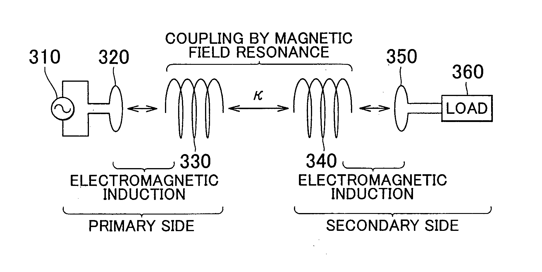
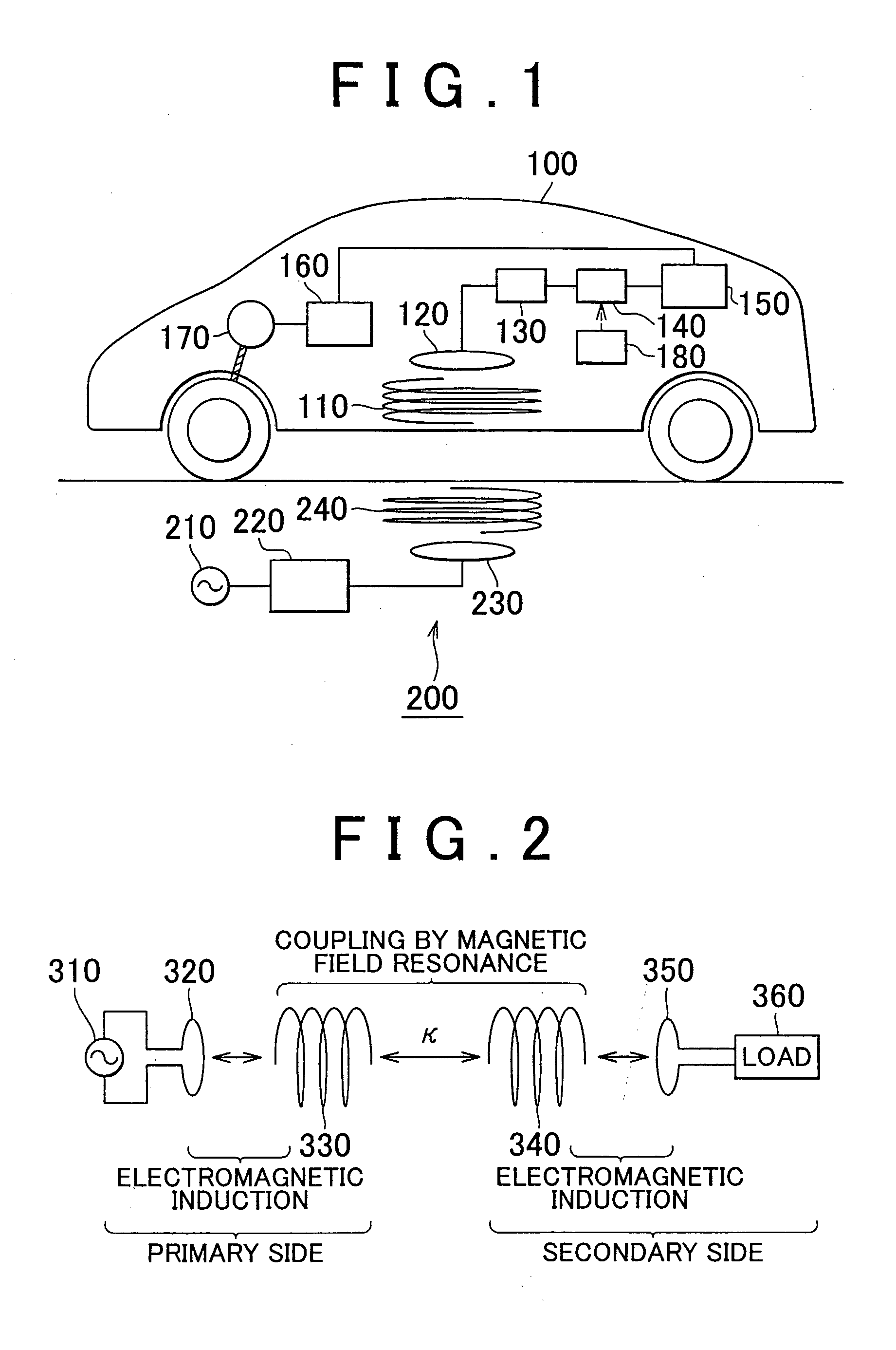
[0060]FIG. 1 is a diagram showing the entire configuration of a basic non-contact power supply system. As shown in FIG. 1, the non-contact power supply system includes a vehicle 100 and a power supply device 200.

[0061]The vehicle 100 includes a secondary resonance coil 110, a secondary electromagnetic induction coil 120, a rectifier 130, a DC-DC converter 140, a power storage device 150, a Power Control Unit (hereinafter, referred to as “PCU”) 160, a motor 170, and a vehicle Electronic Control Unit (ECU) 180.

[0062]The configuration of the vehicle 100 is not limited to the configuration shown in FIG. 1, as long as the vehicle 100 is a vehicle driven by a motor. Examples of the vehicle 100 include a hybrid vehicle including a moto...


PUM


Abstract

A coil unit performs at least one of transmission and reception of electric power using electromagnetic resonance between the coil unit and a primary resonance coil disposed to face the coil unit. The coil unit includes a secondary resonance coil that includes a plurality of coils, and that electromagnetically resonates with the primary resonance coil. A first coil among the plurality of coils is disposed in a manner such that a magnetic field generated by the first coil has a phase opposite to a phase of a magnetic field generated by at least one coil other than the first coil among the plurality of coils, with respect to a plane that faces the primary resonance coil.

Description

BACKGROUND OF THE INVENTION[0001]1. Field of the Invention[0002]The invention relates to a coil unit, a non-contact power transmission device, a non-contact power reception device, a non-contact power supply system, and a vehicle. More particularly, the invention relates to a coil structure that reduces leakage electromagnetic fields that occur when electric power is supplied in a non-contact manner using electromagnetic resonance.[0003]2. Description of the Related Art[0004]Electrically-driven vehicles, such as electric vehicles and hybrid vehicles, have received much attention, as environmentally-friendly vehicles. Each of the electrically-driven vehicles is provided with a motor that generates drive power for driving the vehicle, and a rechargeable power storage device that stores electric power to be supplied to the motor. The hybrid vehicles include a vehicle provided with an internal combustion engine that serves as a power source, in addition to the motor; and a vehicle provi...

Claims


Application Information

Patent Timeline
IPC IPC(8): H02J17/00H02J7/00B60L5/00B60M7/00H01F38/14
CPCB60L5/005B60L11/182H01F38/14Y02T90/14Y02T10/7005Y02T90/122H02J7/025Y02T10/7072B60L53/122H02J50/12H02J50/402Y02T10/70H02J50/70Y02T90/12B60L53/12
Inventor SAKAKIBARA, HIROYUKIICHIKAWA, SHINJI
Owner TOYOTA JIDOSHA KK
Learn More