
Methods and systems for drilling

a drilling method and drilling system technology, applied in the direction of directional drilling, survey, borehole/well accessories, etc., can solve the problems of increasing the cost of drilling a formation, the need for manual control and monitoring, and the inability to repeat drilling performance that relies on manual procedures. to achieve the effect of increasing the flow rate of drilling

Active Publication Date: 2013-02-07
SHELL USA INC
View PDF0 Cites 85 Cited by
  • Summary
  • Abstract
  • Description
  • Claims
  • Application Information

AI Technical Summary

Benefits of technology

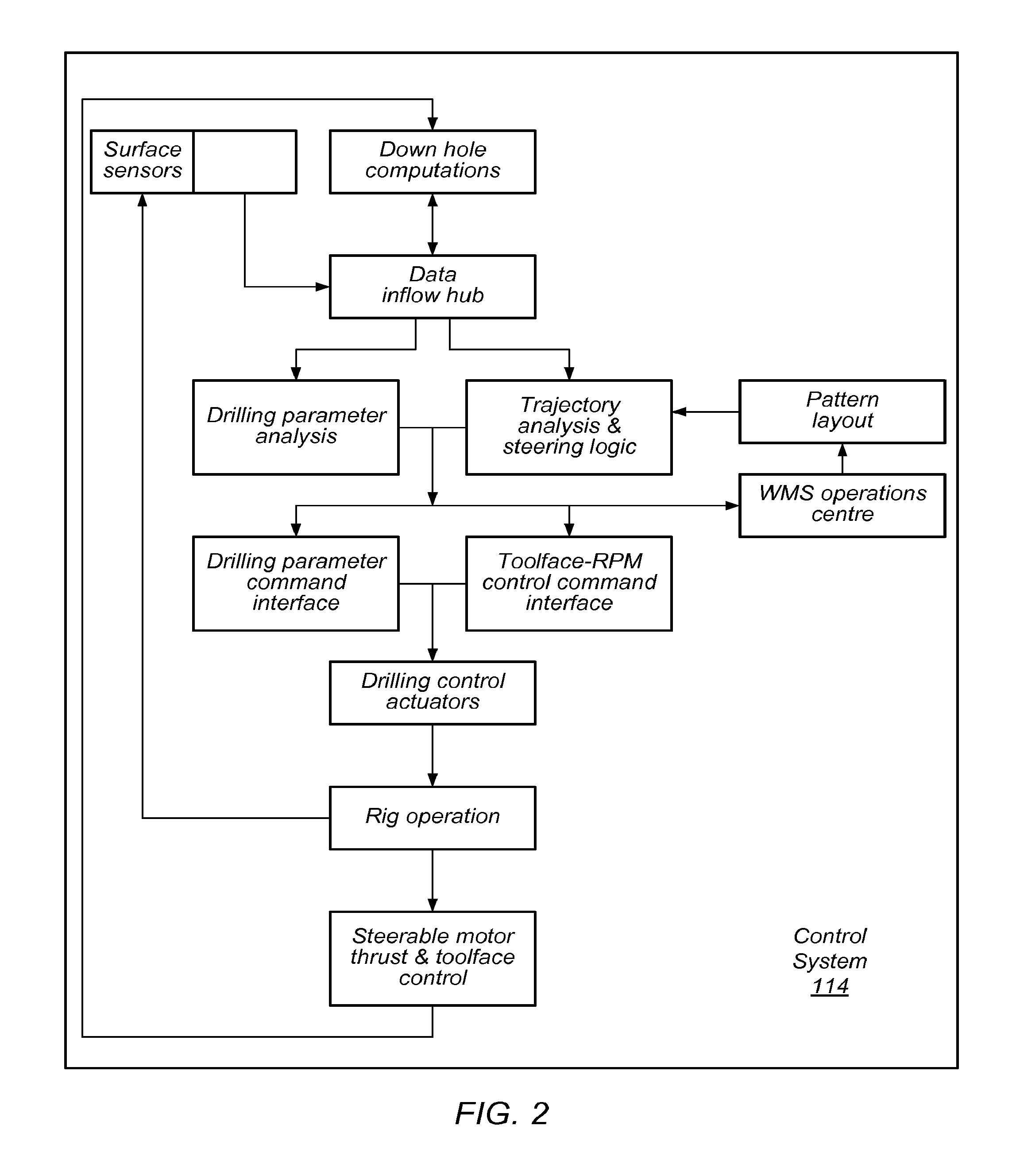
The patent describes systems and methods for automatically drilling in subsurface formations. The methods involve measuring the torque on the drill bit, the pressure across the mud motor, and the flow rate of fluid in the drill string. These measurements are used to assess the weight on the drill bit and the relationship between torque and differential pressure. The methods also involve automatically adjusting the mud motor to maintain the desired pressure and flow rate, and automatically detecting and responding to stalls in the motor. The patent also describes methods for monitoring the performance of the solids handling system and controlling the direction of the drill bit during slide drilling. Overall, the patent provides technical means for automating the drilling process and improving the efficiency of drilling operations.

Problems solved by technology

The need for manual control and monitoring may increase costs of drilling of a formation.
Because different drilling personnel have different experience, knowledge, skills, and instincts, drilling performance that relies on such manual procedures may not be repeatable from formation to formation or from rig to rig.
Suspension of drilling during such operations may reduce the overall rate of progress and efficiency of drilling.
Providing, operating, and maintaining such downhole measuring tools may substantially increase the cost of a drilling system.
In addition, since data from downhole instrumentation must be transmitted to the surface (such as by mud pulsing or periodic electromagnetic transmissions), the downhole instrumentation may provide only limited “snapshots” at periodic intervals during the drilling process.
During the gaps between updates, the information from the downhole instrumentation may become stale and lose its value for controlling drilling.

Method used


Image

  • Methods and systems for drilling
  • Methods and systems for drilling
  • Methods and systems for drilling

Examples


example # 1

Example #1

Start Circulating

[0147]A suction meter and a flowline meter are read and assessed for balance. (There may be a slight discrepancy due to fluid temperature, in that the exiting fluid will be warmer therefore possibly slightly lighter.)[0148]Fluid In / Out: 2 m3 / min×1040 kg / m3=2080 kg / min[0149]Inline fluid viscometer may measure at 600, 300, 200, 100, 6 and 3-rpm readings. The collection time may be 1 second at each rpm speed. 6 seconds to process all six readings.[0150]A temperature correction may be made based a “look-up” table.

example # 2

Example #2

Start Drilling

[0151]A mass of rock generated may be based on rate of penetration and hole size. The calculated mass of rock generated may be graphed in real time.[0152]Hole Size @ 311 mm×ROP @ 100 m / hr=7.59 m3 of cuttings excavated / hr[0153](7.59 m3 / hr×2600 kg / m3) / 60 min=329 kg / min[0154]2600 kg / m3 may be an assumed value for the density of cuttings—alternatively, a density log “look-up” table from offset wells can be used to characterize density for each formation[0155]A look-up table may be provided that includes calliper log data from offset wells to increase accuracy.[0156]A look-up table may be provided that includes a washout percentage vs depth from offset wells.[0157]329 kg / min×5% washout=345 kg / min of rock being generated[0158]A washout percentage may be graphed as a separate set of data points[0159]The lag time may be computed based on the time it takes to empty the annulus of mud calculated from the annular volume and flowrate (a “bottoms up” time)[0160]Cuttings s...

example # 3

Example #3

Mass Balance

[0161]The total mass of fluid going into the well and total mass of fluid exiting the well are metered. The total mass of fluid going into the well is subtracting from the total mass of fluid exiting the well. The difference may indicate the mass of drilled cuttings removed from the well.[0162]Fluid In: 2.0 m3 / min×1040 kg / m3=2080 kg / min[0163]Fluid Out: 2.0 m3 / min×1180 kg / m3=2360 kg / min[0164]The difference is 280 kg / min[0165]By subtracting this difference from the actual mass of rock excavated, an indicator is obtained of a theoretical mass of drilled cuttings that has not been removed from the well.[0166]Therefore 345 kg / min−280 kg / min=65 kg / min left in the well

[0167]In an embodiment, flow measurements may be used to set permissives in the control system. For example, a permissive may be set based on whether the flow coming out of the well is equal to flow going into the well within an established tolerance.

[0168]In some embodiments, performance of a mud solids...


PUM


Abstract

A method of steering a drill bit to form an opening in a subsurface formation, comprises a) determining a distance from design of a well, and b) determining an angle offset from design of the well wherein angle offset from design is the difference between the inclination and azimuth of the hole and the inclination and azimuth of plan, c) wherein at least one distance from design and at least one angle offset from design are determined in real time based, at least in part, on a position of the hole at the last survey, a position at a projected current location of the bit, and a projected position of the bit.

Description

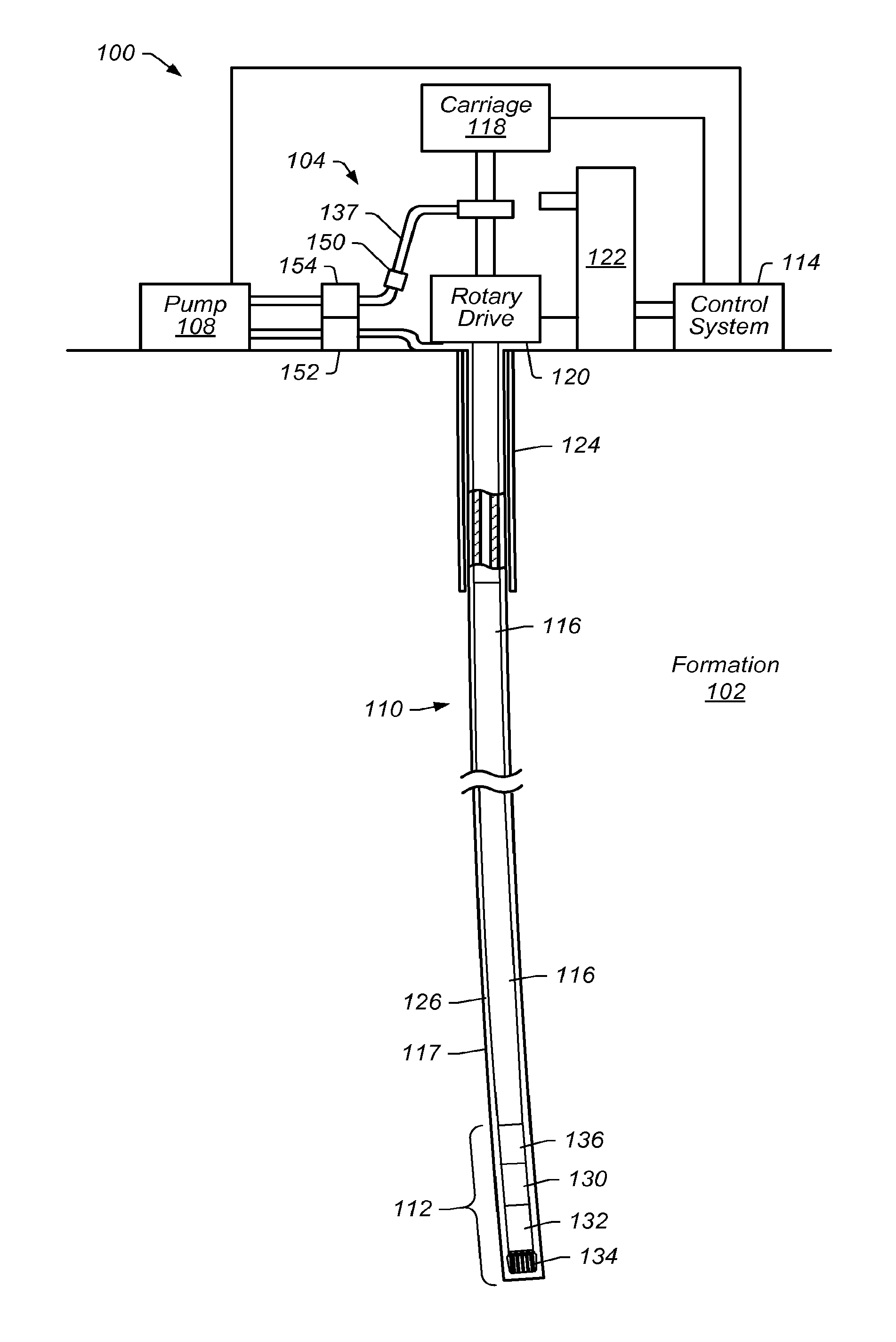
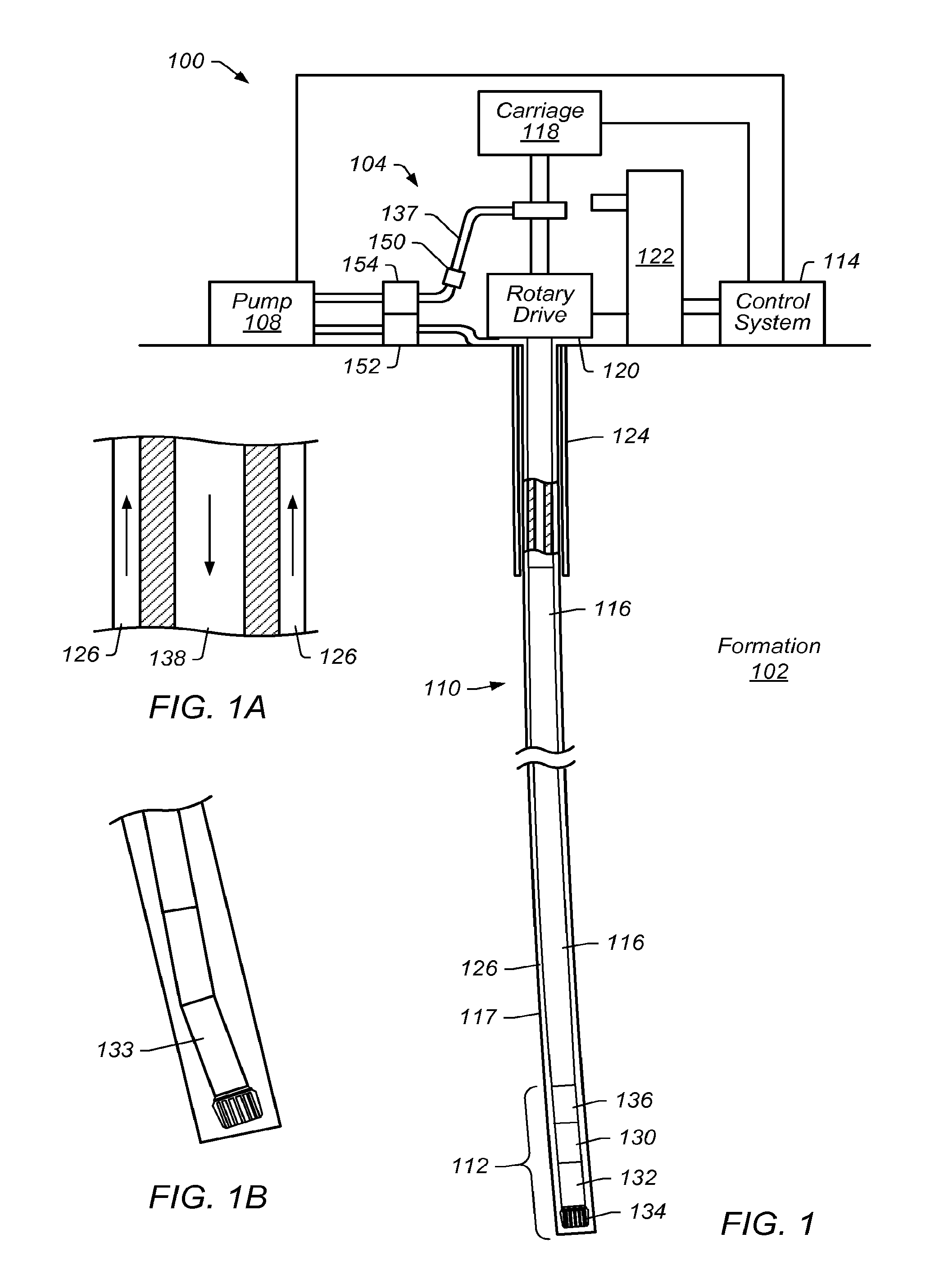
PRIORITY CLAIM[0001]This application is a continuation of International Application PCT / US2011 / 031920, filed Apr. 11, 2011, which claims the benefit of U.S. Provisional Application No. 61 / 323,251, filed Apr. 12, 2010, the entire disclosures of which are hereby incorporated by reference.BACKGROUND[0002]1. Field of the Invention[0003]The present invention relates generally to methods and systems for drilling in various subsurface formations such as hydrocarbon containing formations.[0004]2. Description of Related Art[0005]Hydrocarbons obtained from subterranean formations are often used as energy resources, as feedstocks, and as consumer products. Concerns over depletion of available hydrocarbon resources and concerns over declining overall quality of produced hydrocarbons have led to development of processes for more efficient recovery, processing and / or use of available hydrocarbon resources.[0006]In drilling operations, drilling personnel are commonly assigned various monitoring an...

Claims


Application Information

Patent Timeline
Patent Type & Authority Applications(United States)
IPC IPC(8): E21B44/00E21B7/06
CPCE21B7/06E21B21/01E21B44/00E21B44/02E21B21/08E21B47/0003E21B49/005E21B44/06E21B47/00E21B37/00E21B47/003
Inventor EDBURY, DAVID ALSTONGUERRERO, JOSE VICTORMACDONALD, DUNCAN CHARLESROGERS, JAMES BRYONSITTON, DONALD RAY
Owner SHELL USA INC
Learn More